00196429-0102 - AI Head Reconfiguration Kit SX12 C&P20A_de_en.pdf - 第37页
Introduction Safety Instructions for the Compressed Air Supply Safety Instructions Assembly Instructions / Montageanleitung Head Reconfiguration K it C&P20A 37 Safety Instr uctions for th e Compresse d Air Supply 1.1…

Introduction
Safety Instructions Safety Instructions for Working with Strong Magnetic Fields
36 Assembly Instructions / Montageanleitung Head Reconfiguration Kit C&P20A
Safety Instruc tions for Working with Strong Magnetic Fie lds
1.1.2 Safety Instructions for Working with Strong Magnetic Fields
Safety Instruc tions for the Power Supply
1.1.3 Safety Instructions for the Power Supply
▪ This means that some parts of the system carry potentially lethal voltages - even when switched off
at the main power switch.
▪ Incorrect handling of the placement system can therefore result in fatal injuries, severe injuries or
considerable damage to equipment.
▪ Measurements and maintenance work must always be carried out by appropriately qualified person-
nel.
▪ Always follow the applicable accident prevention and DIN regulations (particularly DIN EN 60 204,
part 1) or the regulations specific to your country.
▪ Before starting any maintenance work, switch off at the main switch and disconnect the machine
from the main power supply.
▪ Always secure the machine against unauthorized reactivation. If these instructions are not followed,
you may be able to touch live parts, which could result in fatal or severe injuries.
Maintaining or replacing assemblies
► End all placement operations on the machine.
► Shut down the Windows operating system correctly, otherwise problems may occur when restarting
or data may be lost.
► Switch the machine off at the main switch.
► Disconnect the machine from the main power supply.
► Switch off the machine and attach warnings signs to indicate that service work is in progress.
DANGER
Strong permanent magnet fields
Fatal hazard: persons with active implants (e.g. pacemakers, defibrillators, insulin pumps etc.)
are at risk from strong permanent magnetic fields inside the machine.
Persons are risk should avoid the immediate vicinity of the machine.
CAUTION
Danger of crushing
Danger of crushing for persons with passive metal implants (e.g. plates, screws).
► Do not reach or lean over into the machine when the protective covers are open.
► Do not bring any metal objects into the hazard area.
CAUTION
Strong permanent magnet fields
There is a risk that the strong magnetic fields could corrupt data on data media or check cards.
► Keep sensitive data carriers away from the permanent magnets.
WARNING
Hazardous Voltages!
The machine is supplied with 3 x 400 V~ (or 3 x 204 V~ / 3 x 230 V~ / 3 x 380 V~ / 3 x 415 V~)
± 5 %, 50/60 Hz mains voltage.
► Observe the safety instructions in the user manual during all service work!
Introduction
Safety Instructions for the Compressed Air Supply Safety Instructions
Assembly Instructions / Montageanleitung Head Reconfiguration Kit C&P20A 37
Safety Instructions for th e Compressed Air Supply
1.1.4 Safety Instructions for the Compressed Air Supply
Safety Instructions for Wo rk on the Cut ting Device
1.1.5 Safety Instructions for Work on the Cutting Device
Safety Instruc tions for the Gantry
1.1.6 Safety Instructions for the Gantry
CAUTION
Risk of injury from compressed air!
Risk of injury when disconnecting the compressed air lines.
► NEVER disconnect compressed air lines while they are still pressurized.
CAUTION
Prolonged interruptions to the compressed air supply can cause damage.
When the machine is switched on, do not use the shutoff valve to interrupt the compressed air
supply for more than 30 minutes.
► If you need to shut off the compressed air system for longer, in order to carry out mainte-
nance or servicing work, you must switch the machine off at the main switch and disconnect
it from the power supply.
WARNING
Risk of injury when working near the cutter.
If you wish to work on the tape cutter, disconnect the machine from the mains supply and com-
pressed air supply.
► Wait until the operating pressure has dropped to 0 MPa.
► Always secure the machine against unauthorized reactivation.
CAUTION
Risk of injury when performing service work on the cutter.
Never support the cutter on your body, e.g., on your knees or thighs. Do not place your feet
under the cutter.
► Wear appropriately thick protective gloves.
► When removing/fitting the cutter, hold it only on the left and right, on the outside.
CAUTION
Moving the gantry can damage the placement head.
When moving the gantry, observe the following:
► NEVER move the gantry by pushing with your hands against the placement head.
► NEVER push the gantry while the Z axis is lowered.
Introduction
Preparatory Work... Safety Instructions for the Gantry
38 Assembly Instructions / Montageanleitung Head Reconfiguration Kit C&P20A
Preparatory Work...
1.2 Preparatory Work...
Purpose and scope
Before performing any preventive maintenance work or service work, a procedure of locking and tagging
must be followed and warning signs must be attached. The procedure, when followed correctly elimi-
nates the possibility of an employee being injured.
Description
Whenever it becomes necessary to isolate, control and release energy, the following procedure is to be
followed.
► Notify affected employees.
► Switch off the machine and all additional devices. Carry out all normal stopping procedures:
⇨ Press the STOP button.
⇨ Shut down the station computer.
⇨ Switch the machine off at the main switch.
► Isolate the machine from all its energy sources:
⇨ Shut off the compressed air supply.
⇨ Shut off the main power supply.
► Lock out the machine.
⇨ Attach a lock wherever possible, e.g. to the main power switch or the motor contactor.
► Alternative: Attaching warning signs
If a machine can be locked, it must be. However, there are situations where energy isolating devices
cannot accommodate locks. In these cases, the energy isolating devices must be tagged to warn
NOTICE
Additional safety measures
These procedures represent the minimum lock/tag out requirements for the machine during
preventive maintenance work and service work. Any additional safeguards needed to complete
work safely can be specified by facilities supervision, the safety officer, the safety committee
and the health department.
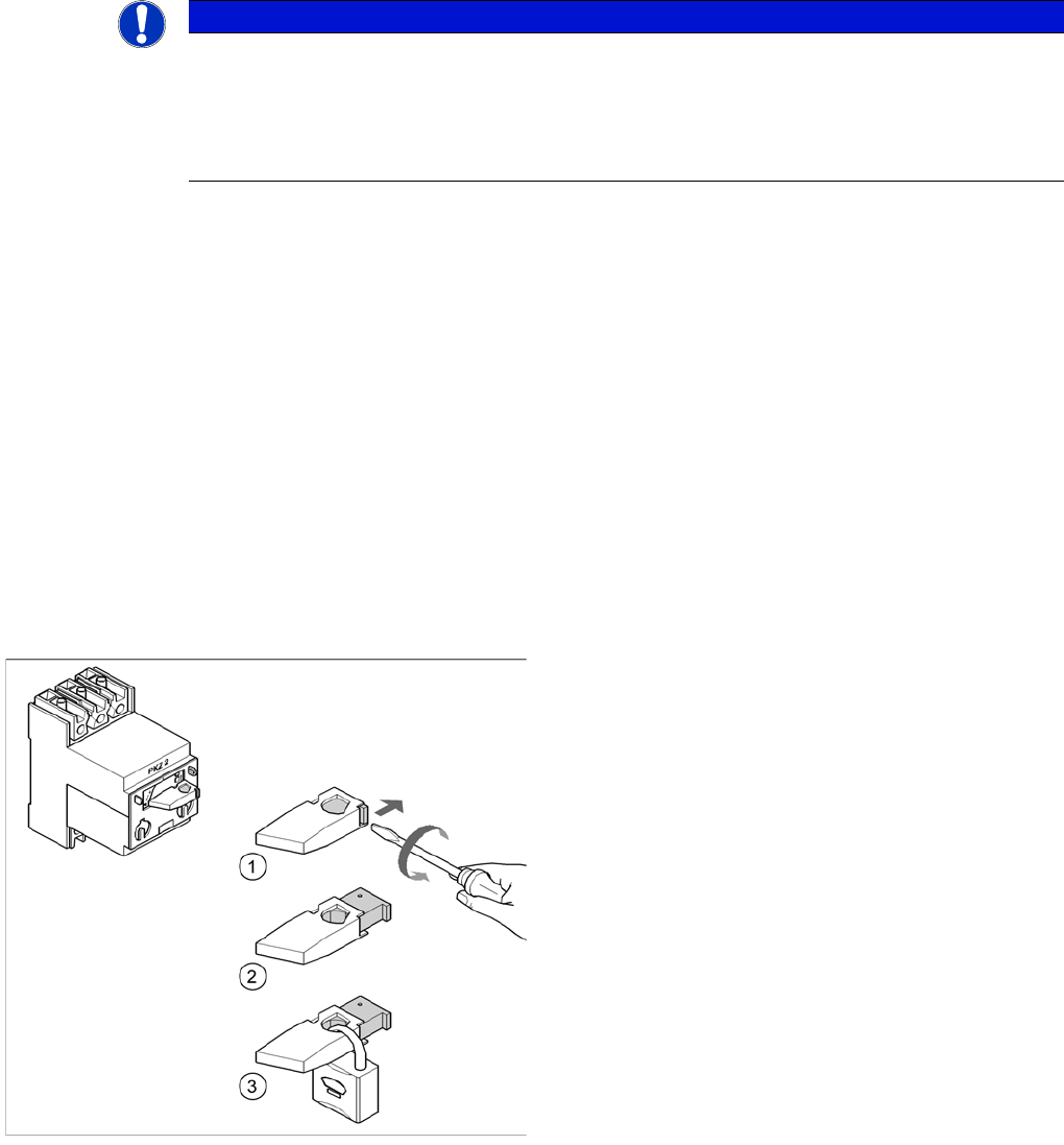
Example: Attaching a padlock to the motor contactor
► Turn the operating lever (1) counterclockwise.
► Use the screwdriver to push the locking lug (2) out of
the operating lever (1).
► Secure the operating lever with a padlock (3).