00196429-0102 - AI Head Reconfiguration Kit SX12 C&P20A_de_en.pdf - 第39页
Introduction Safety Instructions for the Gant ry Preparat ory Work... Assembly Instructions / Montageanleitung Head Reconfiguration K it C&P20A 39 employees that the machine is de -energized for servicing. Th e t ag …
Introduction
Preparatory Work... Safety Instructions for the Gantry
38 Assembly Instructions / Montageanleitung Head Reconfiguration Kit C&P20A
Preparatory Work...
1.2 Preparatory Work...
Purpose and scope
Before performing any preventive maintenance work or service work, a procedure of locking and tagging
must be followed and warning signs must be attached. The procedure, when followed correctly elimi-
nates the possibility of an employee being injured.
Description
Whenever it becomes necessary to isolate, control and release energy, the following procedure is to be
followed.
► Notify affected employees.
► Switch off the machine and all additional devices. Carry out all normal stopping procedures:
⇨ Press the STOP button.
⇨ Shut down the station computer.
⇨ Switch the machine off at the main switch.
► Isolate the machine from all its energy sources:
⇨ Shut off the compressed air supply.
⇨ Shut off the main power supply.
► Lock out the machine.
⇨ Attach a lock wherever possible, e.g. to the main power switch or the motor contactor.
► Alternative: Attaching warning signs
If a machine can be locked, it must be. However, there are situations where energy isolating devices
cannot accommodate locks. In these cases, the energy isolating devices must be tagged to warn
NOTICE
Additional safety measures
These procedures represent the minimum lock/tag out requirements for the machine during
preventive maintenance work and service work. Any additional safeguards needed to complete
work safely can be specified by facilities supervision, the safety officer, the safety committee
and the health department.
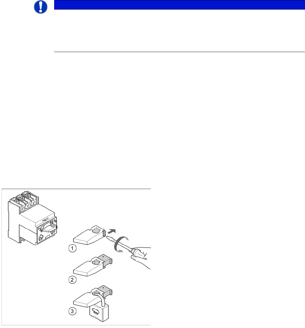
Example: Attaching a padlock to the motor contactor
► Turn the operating lever (1) counterclockwise.
► Use the screwdriver to push the locking lug (2) out of
the operating lever (1).
► Secure the operating lever with a padlock (3).
Introduction
Safety Instructions for the Gantry Preparatory Work...
Assembly Instructions / Montageanleitung Head Reconfiguration Kit C&P20A 39
employees that the machine is de-energized for servicing. The tag or label must be securely fas-
tened, it must be placed in a position visible to all and it may only be removed by the person who
attached it.
► Release of stored energy
Stored energy in the compressed air supply or electrical energy in electrolytic capacitors must be
released by appropriate means.
⇨ After switching off the machine, wait until the voltages and the compressed air have discharged,
so that work can be performed without any risk.
► Testing the lock out.
Testing the lock out can be done simply by pressing the start button.
► The following steps must be taken to restore the machine to operation.
► Check the working area. Authorized employees should remove all of their tools and reinstall all safety
features.
► Notify all affected employees.
► Before removing even one lock or tag, inform all workers in the affected area that the machine is
going to be restarted.
► Remove locks/tags
► Every authorized employee must remove his own lock and shut it away.
► Turn the machine on. Make sure that authorized staff check the equipment in operation to ensure
that repairs were done correctly
Testing
Service personnel may test circuits by energizing them briefly without suspending the Lock Out / Tag
Out Procedure. This may only be done when no other work is being performed by any other person on
the equipment being tested.
It is extremely important that all remote start switches be tagged with the "Do Not Operate" tag to prevent
inadvertent operation of the equipment during these periods.
Responsibilities
▪ It shall be the responsibility of the maintenance and service personnel to make sure this procedure
is adhered to.
▪ It shall be the responsibility of the maintenance and service personnel's immediate supervisor to in-
struct his personnel on this procedure.
▪ It shall be the responsibility of the Safety Officer with assistance from the Safety Committee, Health
Service Department, and the various managers and vice-presidents to administer the Lock Out / Tag
Out Procedure.

Introduction
Abbreviations Safety Instructions for the Gantry
40 Assembly Instructions / Montageanleitung Head Reconfiguration Kit C&P20A
Abbreviations
1.3 Abbreviations
Abbreviations Description
PA Placement area
CO Component
COT Changeover table
COT-i Changeover table insert
C&P Collect&Place
C&P12, CP12 Collect&Place head with 12 segments
C&P20, CP20 Collect&Place head with 20 segments
C&P6, CP6 Collect&Place head with 6 segments
CPP Collect&Pick&Place head
CPx Collective term for CPP, CP20, CP12 and/or CP6
DC Dual conveyor with 2 lanes
ESD Electrostatic sensitive device
EMC Electromagnetic compatibility
SC Single conveyor with 1 lane
FHE Fast Head Exchange
PCB Printed circuit board
P&P Pick&Place
QC Quad lane conveyor with 4 lanes
SCS Single Core Solution
SC Station computer
TH TwinHead
VS Vision system
WPC Wafflepack Changer
WPC4 Waffle Pack Changer Version 4
WPC5 Wafflepack Changer Version 5
WPC6 Waffle Pack Changer Version 6