00196429-0102 - AI Head Reconfiguration Kit SX12 C&P20A_de_en.pdf - 第49页
Installing the C&P20A Placement Head Removing CPP Head Disassembling the CPP Placement Head Assembly Instructions / Montageanleitung Head Reconfiguration K it C&P20A 49 Removing CPP Head 3.2.2 Removing CPP Head F…
Installing the C&P20A Placement Head
Disassembling the CPP Placement Head Saving the Existing Machine Data
48 Assembly Instructions / Montageanleitung Head Reconfiguration Kit C&P20A
Saving the Existing Machine Data
3.1.2 Saving the Existing Machine Data
► Insert a USB stick or another appropriate storage medium into the USB slot of the station computer.
► Save the machine data to the storage medium. Select Service --> Archive machine data...
Docking Out the Component Trolley and Switching Off the Machine
3.1.3 Docking Out the Component Trolley and Switching Off the Machine
► Dock out the component trolleys.
► Shut down the station computer and switch off the machine at the main switch.
► Disconnect the machine from the main power and the pneumatic supplies.
► Always secure the machine against unauthorized reactivation. See "1.2 Preparatory Work..." [➙ 38].
Disassembling the CPP Placement Head
3.2 Disassembling the CPP Placement Head
Disconnecting Data and Pneumatic Lines
3.2.1 Disconnecting Data and Pneumatic Lines
CAUTION
► You must wear the ESD armband during all work on the placement head.
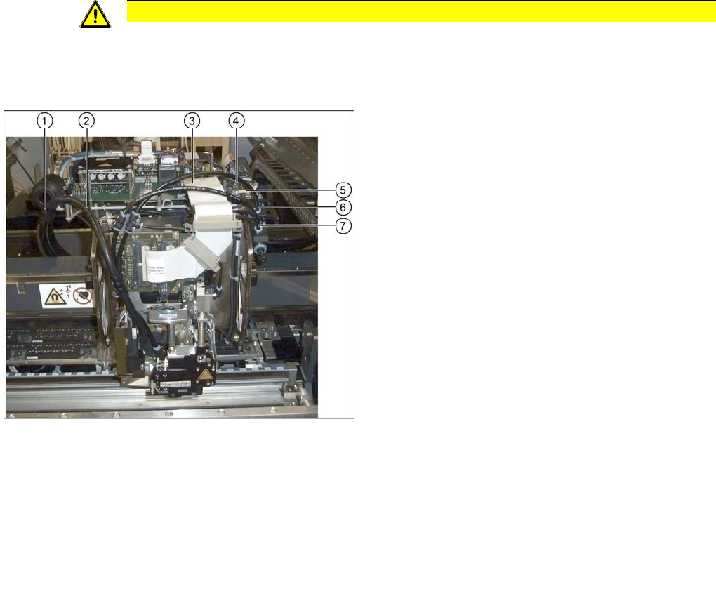
Disconnecting data and pneumatic lines
Legend
1. Cover cap on the silencer
2. Discharged air hose to silencer
3. Flat ribbon cable to the head adapter
4. Component camera connector
5. Cable holder of the component camera cable
6. Pneumatic hose of the pickup / placement circuit
7. Pneumatic hose of the holding circuit
► Disconnect the discharged air hose (2) on the silenc-
er.
► Remove the cover cap when converting to a Twin-
Head (1).
► Unplug the flat ribbon cable from the head adapter
(3).
► Disconnect the two connectors from the component
camera (4).
► Remove the cable holder (strain relief) of the compo-
nent camera cable (5).
► Disconnect the pneumatic hoses of the pickup /
placement circuit (6) and the holding circuit (7) from
the compressed air distributor.
► Remove all blanking plugs on the compressed air dis-
tributor when converting to a TwinHead.
Installing the C&P20A Placement Head
Removing CPP Head Disassembling the CPP Placement Head
Assembly Instructions / Montageanleitung Head Reconfiguration Kit C&P20A 49
Removing CPP Head
3.2.2 Removing CPP Head
Further Aspects for the C onfigurati on
3.2.3 Further Aspects for the Configuration
The following points have to be observed when replacing a CPP head by a C&P20A head:
▪ The existing head adapter can be kept.
▪ The CPP nozzle magazines are to be replaced by DC&P20A nozzle magazines. The basic nozzle
changer body on SX machines is identical for both head types.
▪ The reject bin and the nozzle station can still be used.
Continue with section "3.4 Assembly of the C&P20A Placement Head" [ ➙ 53].
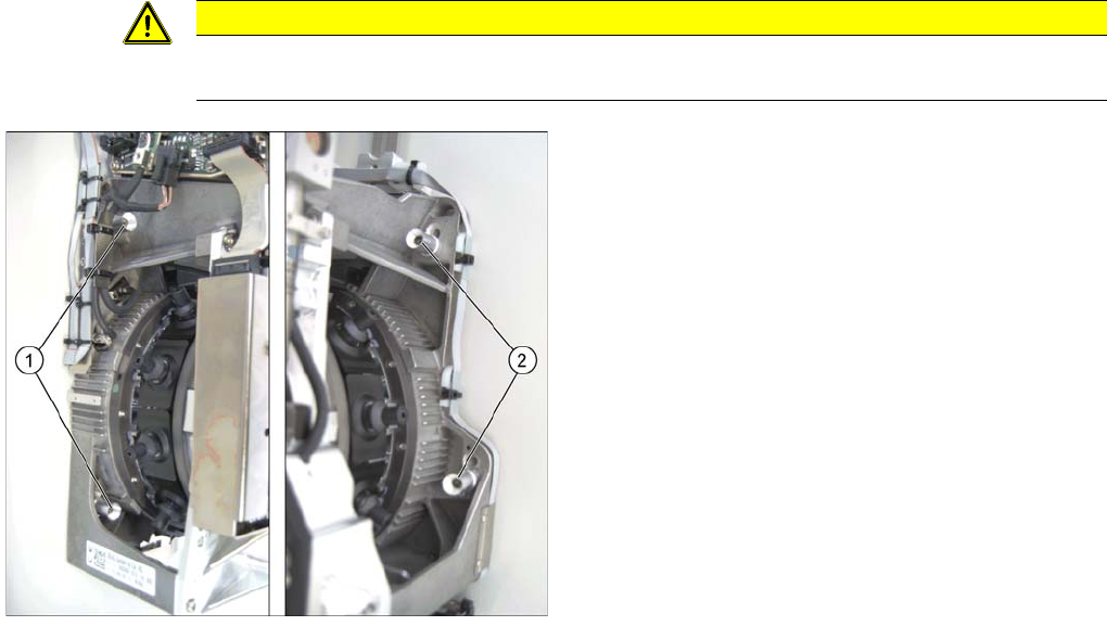
CAUTION
► Firmly hold the placement head at its handle when loosening the fixing screws to prevent
the head from falling and avoid a possible damage.
Legend
1. Fixing screws on the left side
2. Fixing screws on the right side
In this graphic the fixing screws are shown in the "head
top" position.
► Loosen the four fixing screws of the CPP head (the
screws stay in the sockets).
► Lift the CPP head out of the machine.
Installing the C&P20A Placement Head
Disassembling the TwinHead Further Aspects for the Configuration
50 Assembly Instructions / Montageanleitung Head Reconfiguration Kit C&P20A
Disassembling the TwinHead
3.3 Disassembling the TwinHead
The TwinHead consists of 2 identical Twin segments, which are fitted at an angle of 180° to one another.
When changing over to another placement head type both segments must be removed.
Parts, Equipment and Tools
▪ Torque screwdriver 100-500 Ncm [03078400-xx]
Removal
CAUTION
► You must wear the ESD armband during all work on the placement head.
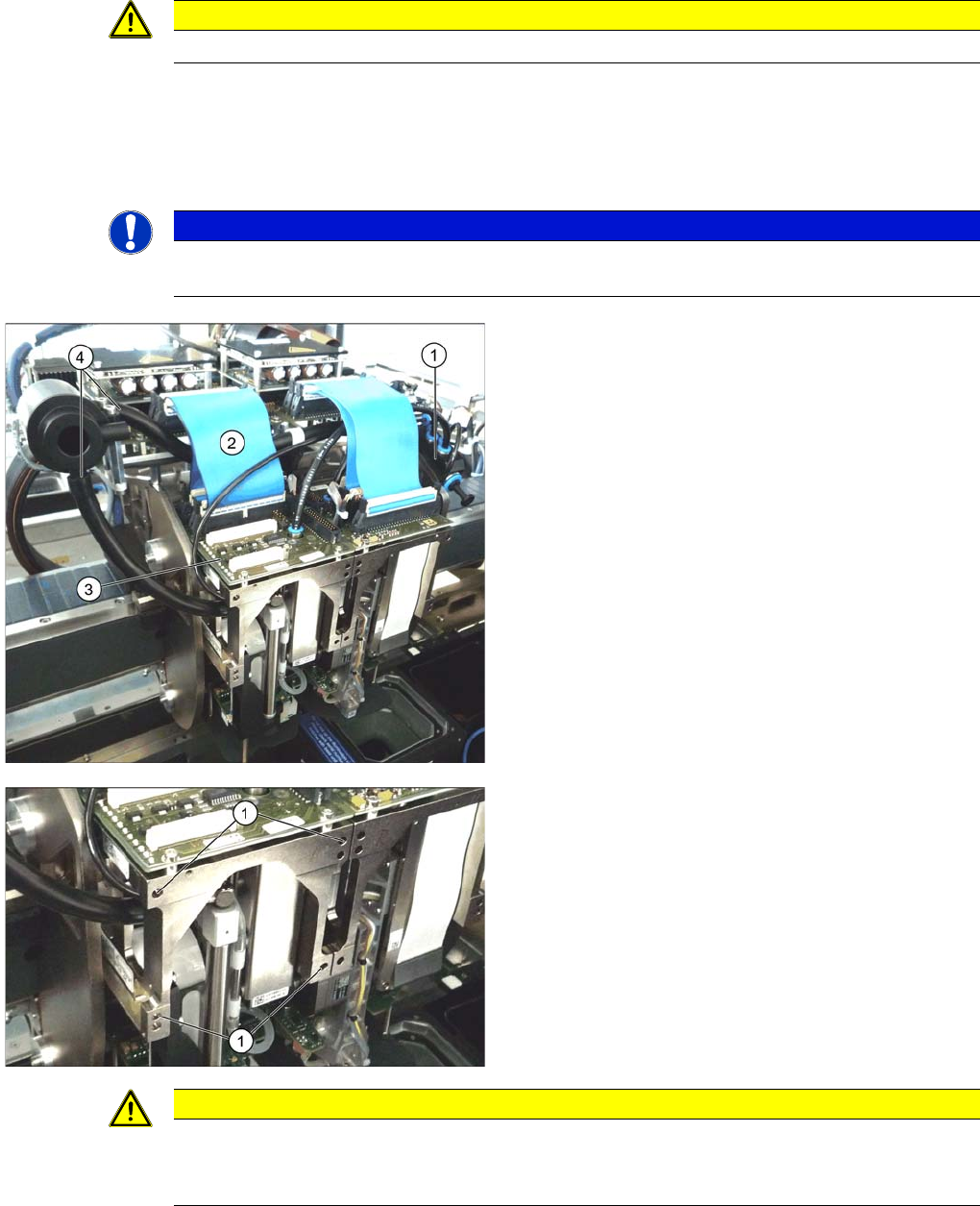
NOTICE
The removal procedure is described here for module 1 (left). Repeat the procedure for
module 2 (right).
► Move the gantry into a position which allows you best
access.
► Unplug the pneumatic connection from the TwinHead
vacuum generator to the pneumatic distributor (1)
and the silencer.
► Remove both discharged air hoses from the silencer
(4).
► Unplug the pneumatic connection from the pneumat-
ic distributor (1) to the TwinHead return cylinder.
► Unplug the flat ribbon cable (2) from the head main
board (3) on the TwinHead.
Each module is fixed with 4 screws to the head plate and
is positioned with two pins.
► Loosen the 4 M4x14 fixing screws (1) with a long Al-
len key.
► Pull the module out of the locating pins.
► Remove module 2 the same way.
CAUTION
Removal instruction
The individual modules are not secured with a hook like it is the case for the C&P20A and the
CPP head. They can fall down.