00196429-0102 - AI Head Reconfiguration Kit SX12 C&P20A_de_en.pdf - 第55页
Installing the C&P20A Placement Head Height Adjustment and Installatio n of the Nozzle Station Assembl y of the C&P20A Placement Head Assembly Instructions / Montageanleitung Head Reconfiguration K it C&P20A …
Installing the C&P20A Placement Head
Assembly of the C&P20A Placement Head Connecting the C&P20A Head
54 Assembly Instructions / Montageanleitung Head Reconfiguration Kit C&P20A
Connecti ng the C&P20A Hea d
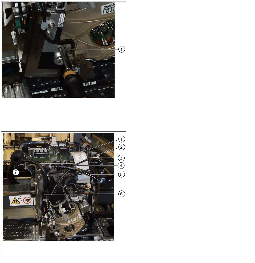
3.4.2 Connecting the C&P20A Head
► Connect the flat ribbon cable to the head and the base adapter (1).
► Fix the strain reliefs of the component camera cables (2 and 3) and connect the cables to the vision
board.
► Connect all pneumatic connections to the C&P20A (4 and 5) and to the compressed air distributor.
► Connect the discharged air hose to the silencer (6).
► Close the lower connection at the silencer with the cover cap [03006728-xx].
Tightening the covered head screw
One of the four head screws by means of which the
C&P20A head is fixed to the head plate is located behind
the pressure control valve. The pressure control valve
has to be swivelled to the left to gain access.
The covered head screw can now be accessed via a
guide drilling.
► Insert the Torx screwdriver into the guide drilling and
push it backwards until it sets down on the the head
screw.
► Tighten the covered head screw M4X14.
Connecting lines
Legend
1. Flat ribbon cable [03065867-xx]
2. Strain relief component camera cable
3. Strain relief component camera cable
4. Hose / Pressure control valve C+P20 [03016216-xx]
5. ESD tube / holding circle C+P20 [03070202-xx]
6. Discharged air hose to silencer
7. Cover cap [03006728-xx]
Installing the C&P20A Placement Head
Height Adjustment and Installation of the Nozzle Station Assembly of the C&P20A Placement Head
Assembly Instructions / Montageanleitung Head Reconfiguration Kit C&P20A 55
Height Adjustment and Installation of the Nozzle Station
3.4.3 Height Adjustment and Installation of the Nozzle Station
The nozzle station [03073328-xx] is included in the parts set.
When replacing a C&P20A head by a CPP head and vice versa the present nozzle station can be kept.
When replacing a TwinHead by a CPP or a C&P20A head the nozzle station of the parts set must be
installed.
Height Adjustment of the Nozzle Statio n
3.4.3.1 Height Adjustment of the Nozzle Station
CAUTION
► If the COT insert has been removed or shifted during the conversion, the installation height
of the nozzle station should be checked in any case.
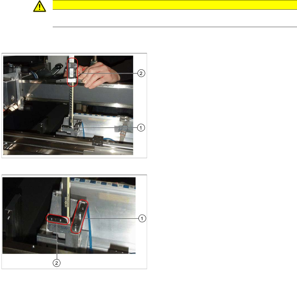
Measuring the height of the nozzle station
► Push the placement head to be measured outwards.
► Place the caliper perpendicularly on the contact sur-
face of the reject station (1) and measure the dis-
tance to the guide rail of the gantry.
This distance must be 189mm ± 0.2mm (2).
► If the distance is correct, proceed with the installation
of the nozzle station.
Position for the shim plates
► If the distance is too large, insert shim plates: Shim
plates for nozzle stripping device [03039514-xx and
03021079-xx], screws DIN7991 M4x20 - 8.8
[00333782-xx].
► If the distance is too small because shim plates have
already been inserted, remove these.
Installing the C&P20A Placement Head
Assembly of the C&P20A Placement Head Height Adjustment and Installation of the Nozzle Station
56 Assembly Instructions / Montageanleitung Head Reconfiguration Kit C&P20A
Installing the Nozzle Station
3.4.3.2 Installing the Nozzle Station
► Remove the downholder on the right above the reject bin.
► Fasten the downholder left [03079173-xx] above the reject bin [03048638-xx] (see "3.4.3.3.2 Install-
ing/Removing Downholder" [ ➙ 58]).
► Insert the coding sheet at unoccupied bin locations [03083883-xx] (see "3.4.3.3.3 Installing/Remov-
ing Coding Sheet" [ ➙ 59]).
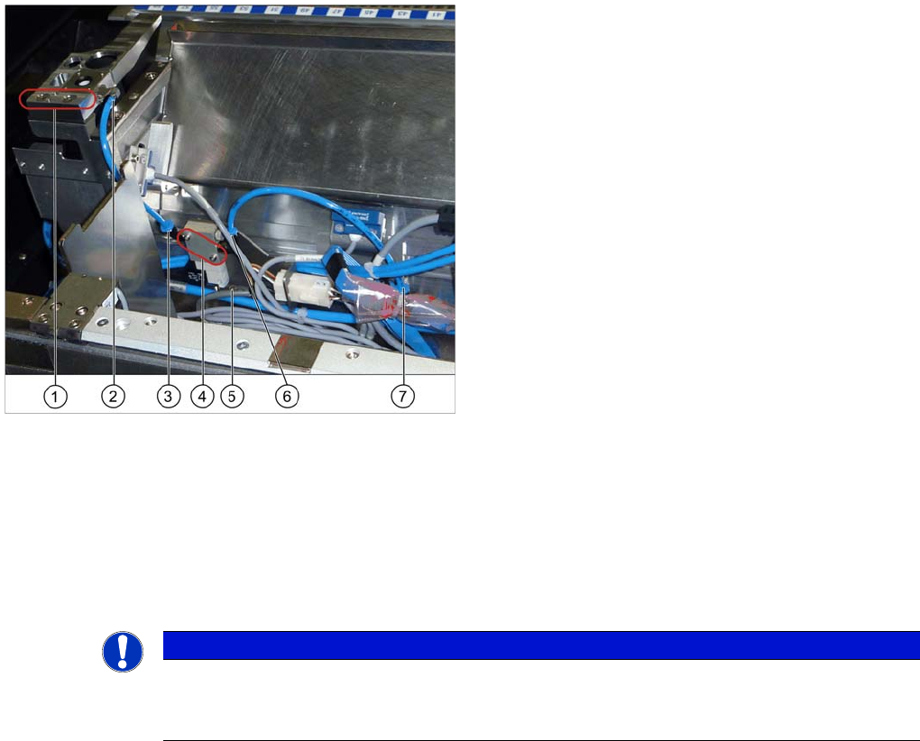
► Install the valve for the nozzle station [03055785-xx] (4) at the COT insert using the two DIN912-
M2,5 x 16-A2-70 screws [00350291-xx].
► Replace, unless already performed, the QSC-6H plug at the solenoid valve feed control with the Y
press-fit connection with push-on socket QSY-6H-4 [03055792-xx].
► Plug the hose PUN-CM 4x0.75 / 200mm [03056096-xx] into the pneumatic connection to the nozzle
changer (5) and into the pneumatic connection of the nozzle changer (6) or close it with the plug
QSC-4H [00330249-xx].
► Plug the hose PUN-CM 4x0.75 / 135mm [03056097-xx] into the pneumatic connection to the nozzle
changer [03055785-xx] (3) and to the pneumatic connection of the nozzle changer (2).
► Connect the cable "Cable feed X series: nozzle station" [03053223-xx] which has already been con-
nected in the COT insert with the "valve for nozzle station cplt." [03055785-xx].
► If the verify reject bin option is already installed, the sensor for this reject bin has to be installed at
another position. For this, use the metal sensor MK2 prefitted (reject bin 6x6) [03080138-xx]. For fur-
ther information please refer to the Assembly Instructions Reject Bin SIPLACE SX1/2 [00196615-
xx].
See also
3.4.3.3 Installing the Downholder and the Coding Sheet [ ➙ 57]
Installing the nozzle station
1. Fixation points of the nozzle station [03073328-xx]
2. Pneumatic connection on the nozzle station
3. Pneumatic connection to the nozzle station
4. Valve for the nozzle station [03055785-xx]
5. Pneumatic connection to the nozzle changer
6. Fixing screw of the mounting plate
7. Pneumatic connection on the nozzle changer
► Fit the nozzle station [03073328-xx] with two screws
in its mounting position (1).
► Depending on the machine configuration (see
"3.4.3.3.1 Configurations with Reject Bins and Cod-
ing Sheet" [➙ 57]) insert the reject bin [03048638-xx]
and the component reject bin up to 6x6 [03062378--
xx]. The reject bin mustn't be higher than the convey-
or side wall in any case.
NOTICE
The mounting plate for the solenoid valve is fastened and fixed in position with one screw only
(6). If necessary, loosen this mounting plate to install the solenoid valve.
Attention: the connector left to the solenoid valve is also fastened to this plate.