00196429-0102 - AI Head Reconfiguration Kit SX12 C&P20A_de_en.pdf - 第60页
Installing the C&P20A Placement Head Assembly of the C&P20A Placement Head Settings On the Base Adapt er 60 Assembly Instructions / Mont ageanleitung Head Reconfiguratio n Kit C&P20A Settings On the Ba se Ada…
Installing the C&P20A Placement Head
Height Adjustment and Installation of the Nozzle Station Assembly of the C&P20A Placement Head
Assembly Instructions / Montageanleitung Head Reconfiguration Kit C&P20A 59
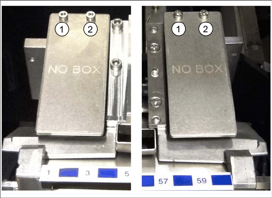
Installing/Removing Coding Sheet
Installing/Removing Coding Sheet
Coding sheets are used on unoccupied bin locations.
Installing coding sheet
Coding sheet left and right
► Fasten the coding sheet [03083883-xx] directly on cast part of the used tape channel using two
screws (1 and 2).
No shim plates are required.
Removing coding sheet
When exchanging the placement head type it may be necessary, depending on the new configuration,
to remove downholders and reject bins and replace them by coding sheets on unopccupied bin locations.
The configurations with reject bins, downholders and coding sheets are described in the relevant assem-
bly instructions ([00196429--xx] for changeover to C&P20A, [00196430-xx] for changeover to CPP and
[00196431--xx] changeover to TwinHead).
► Remove the two screws (1 and 2) and lift off the coding sheet.
Installing the C&P20A Placement Head
Assembly of the C&P20A Placement Head Settings On the Base Adapter
60 Assembly Instructions / Montageanleitung Head Reconfiguration Kit C&P20A
Settings On the Ba se Adapter
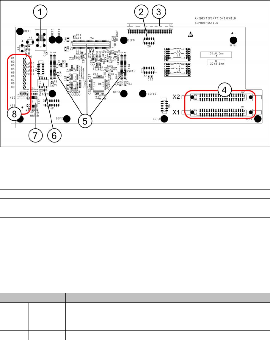
3.4.4 Settings On the Base Adapter
Base adapter for CPP and C&P20A heads (without HCU)
Legend
Switch S1
This switch sets the intermediate circuit voltage for the Z axis.
▪ The switch must be set to 40 V for C&P20 heads.
▪ The setting must be 150 V for CPP heads.
If the setting is incorrect, no damage will be done but an HCU error message will be issued.
DIP switch S2
All switches must be set to OFF. The HCU can be reset with S3, if necessary.
1 Switch S1 (see below) 2 X4 – for checking the voltages
3 Connection to the head interface C700 4 X1 and X2 – to the head
5 X4, X14 and X15 – for the HCU 6 DIP switch S2
7 7 segment display 8 LEDs H1-H11
Switches Description
S1 S0 Gantry encoding (currently not in use)
S2 S1 Gantry encoding (currently not in use)
S3 Reset Reset HCU
S4 Boot Activation of bootstrap function for the HCU (not designed for Service)
Installing the C&P20A Placement Head
Connections on the Hotlink Card (Box PC) Assembly of the C&P20A Placement Head
Assembly Instructions / Montageanleitung Head Reconfiguration Kit C&P20A 61
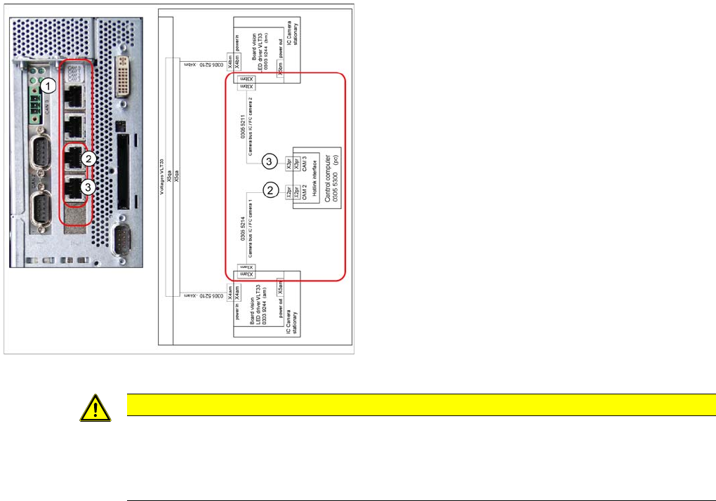
Connecti ons on the Hotlink Card (B ox PC)
3.4.5 Connections on the Hotlink Card (Box PC)
► Insert a USB stick or another appropriate storage medium into the USB slot of the station computer.
► Save the machine data from the storage medium to the station computer.
Connections on the hotlink card
Legend
1. Hotlink connections CAM 0 to CAM 3 at the BOX PC.
2. CAM 2 - X2pr
03055214: stationary IC / FC camera 1
3. CAM 3 - X3pr
03055211: stationary IC / FC camera 2
► Plug in the Hotlink cable for the relevant component
camera.
CAUTION
The Hotlink cables of the IC and FC cameras must be unplugged for the placement area in
which there is a C&P20A or a CPP head if no stationary camera is used here.
Do not connect the Hotlink cables which are not in use!
Do not confuse the Hotlink cables with the twisted pair cables!