4OM-1064-001.pdf - 第101页
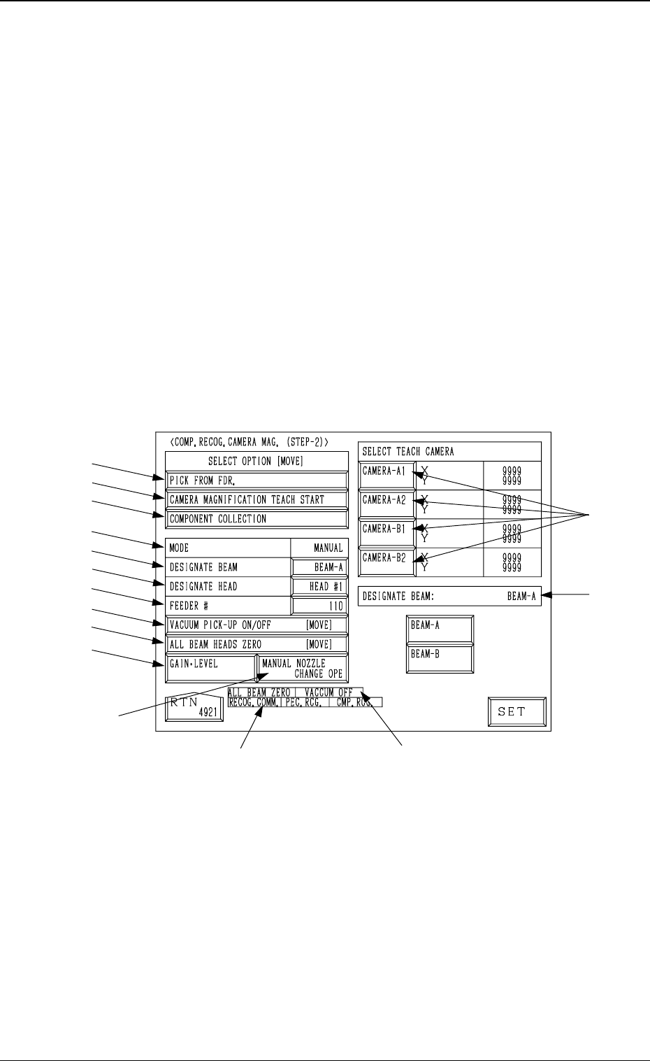
Tg0249-PM-MM 6. 2 COMP . RECOG. CAMERA MAG. (STEP-2) Display • This display allows teaching the magnification of the component recogni- tion camera. The offset values are calculated by recognizing the printed pattern on …

Tg0249-PM-MM
Operation Procedure
• Required Item
Special Jig P.C.B. (Option): P.C.B. Recognition Calibration Jig (JG-0086)
(1) Check the followings.
• Check that the machine is powered.
• Check that the supply cover is completely closed.
(2) Set “PLACE REF.” in the “P.C.B. LOCATE MODE” data box at the
“P.C.B. TRANSFER MODE SET-UP” Display. (Hierarchical Sequence:
“DATA EDIT” Display → “DEVICE DATA” Display → “P.C.B. TRANS-
FER MODE SET-UP” Display)
(3) Set parameters in the data boxes related to the special jig P.C.B. (option)
at the “JIG P.C.B. EDIT” display. Hierarchical Sequence: “SPECIAL
SEL.” Display → “TEACH OFFSET” Display → “P.E.C. RECOG CAM-
ERA & BEAM OFFSET (STEP-1)” Display → “JIG P.C.B. EDIT” Dis-
play)
Enter the numerical values related to the mark on the P.C.B. positioning
reference side in the “X” and “Y” data boxes of the label “MARK #1 (PP.
BASIS)”.
(4) Detach the P.C.B. support pins at the “PCB SUPPORT PINS SET-UP
MODE” display. (Hierarchical Sequence: “MANUAL MODE” Display
→ “PCB SUPPORT PINS SET-UP MODE” Display)
(5) Set “160 mm” in the “X” and “Y” data boxes of the label “P.C.B. SIZE”
at the “CONVEYOR WIDTH” display. Then, select the [DESIGNATE
WIDTH [MOVE]] key and press the [MOVE] button.
(6) Attach the P.C.B. support pins at the “PCB SUPPORT PINS SET-UP
MODE” display. (Hierarchical Sequence: “MANUAL MODE” Display
→ “PCB SUPPORT PINS SET-UP MODE” Display)
(7) Press the [TRANSFER] key at the “P.C.B. TRANSFER OPERATION”
display to position the jig P.C.B.
Use the menus at the “PCB SUPPORT PINS SET-UP MODE” display to
confirm that the jig P.C.B. is securely fixed.
(8) Select the [ALL BEAM HEADS ZERO [MOVE]] key and press the
[MOVE] button to zero all beam heads.
(9) To specify the gain and level, use the “GAIN
LEVEL” display.
Note: In normal cases, set “DISABLE” in the “DESIGNATE” data box.
(10) Select the item to be taught and press the [MOVE] button.
The machine starts the teaching operation (automatic).
0004-002 3-54
6. TEACH OFFSET Display
Tg0249-PM-MM
6.2 COMP. RECOG. CAMERA MAG. (STEP-2) Display
• This display allows teaching the magnification of the component recogni-
tion camera.
The offset values are calculated by recognizing the printed pattern on the
special jig (option) picked up by a nozzle with the component recognition
camera.
Note: (a) A special jig (option) is required.
The parameters are factory-set at shipment. Normally, it is not nec-
essary to teach these parameters.
(b) Follow the teaching procedures in the specified order. Otherwise,
some trouble (such as inaccurate component placement, frequent
mechanical errors, etc.) will arise.
When the [COMPONENT RECOG CAMERA MAGNIFICATION (STEP-
2)] key is pressed at the “TEACH OFFSET” display, the following display
appears on the screen.
*12
*13
*15
*14
*1
*2
*3
*4
*5
*6
*7
*8
*9
*10
*11
9910-001 3-55
6. TEACH OFFSET Display
Fig. 3.36
Tg0249-PM-MM
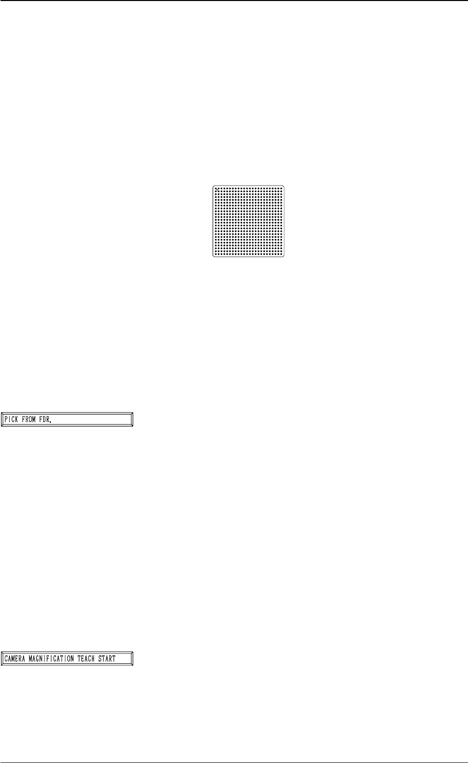
Special Jig (Option)
Notes: (a) Consult our sales personnel for the detailed in-
formation on how to use the special jig compo-
nent.
(b) Handle this fragile jig very carefully.
Name : Component Recognition Calibration Jig
Model Name : JG-0084
Dimensions : Approx. 50 (width) × 50 (depth) × 1.5 mm
(thickness)
• The jig component has a pattern of round marks printed on
the opal glass, forming a grid (matrix) and the pattern is
used to calculate the magnification.
• Only the “MF01”, “MF02” or “MA06” must be used to pick
up this special jig.
• The jig must be attached to or detached from the nozzle by
hand.
*1 [PICK FROM FDR.] Key
The machine works to pick up the special jig.
When this key is selected and the [MOVE] button is pressed,
the machine performs the pick-up operations.
The head moves down to the pick-up point over the desig-
nated feeder and stops.
The [VACUUM PICK-UP ON/OFF [MOVE]] key must
be selected and the [MOVE] button must be pressed to turn
on the vacuum. Then, the special jig must be attached to
the head by hand with the printed mark side facing down-
ward.
Note: When the special jig must be attached to the head
by hand, special care is required for safety pur-
poses because the operator has to put part of his/
her body inside the machine.
*2 [CAMERA MAGNIFICATION TEACH START] Key
The machine works to teach the magnification of the se-
lected component recognition camera.
When this key is selected and the [MOVE] button is pressed,
the machine starts the teaching operation.
Note: Before performing the teaching operations, be sure
to make the nozzle pick up the special jig and zero
both beams.
9910-001 3-56
6. TEACH OFFSET Display
Fig. 3.37