4OM-1064-001.pdf - 第107页
Tg0249-PM-MM 6.3 COMP . RCG. CAMR. OFST . (STEP3) Display • This display allows teaching the offset data of the component recognition camera. The offset values are calculated by recognizing the printed pattern on the jig…

Tg0249-PM-MM
(7) Select the [PICK FROM FDR.] key and press the
[MOVE] button.
The head moves to the designated position and stops.
(8) Set the [OPERATION/SET UP] switch to the “SET UP”
side and press the [READY] button to turn off the LED.
(9) Open the supply cover.
(10) Select the [VACUUM PICK-UP ON/OFF [MOVE]] key
and press the [MOVE] button to turn on the vacuum.
(11) Attach the special jig (option) to the head by hand.
Notes: (a) Be sure to make the nozzle pick up the cen-
ter of the special jig with the printed mark
side facing downward.
(b) Do not touch the printed mark side with your
finger.
CAUTION
Special care is required for
safety purposes because the
operator has to put part of his/
her body inside the machine.
(12) Close the supply cover.
(13) Press the [READY] button to turn on the LED and set the
[OPERATION/SET UP] switch to the "OPERATION"
side.
(14) Select the [CAMERA MAGNIFICATION TEACH
START] key and press the [MOVE] button. The machine
starts the teaching operations.
(15) When the teaching is completed, select the [COMPO-
NENT COLLECTION] key and press the [MOVE] but-
ton.
The head moves to the designated position and stops.
(16) Set the [OPERATION/SET UP] switch to the "SET UP"
side and press the [READY] button to turn off the LED.
(17) Open the supply cover.
(18) Select the [VACUUM PICK-UP ON/OFF [MOVE]] key
and press the [MOVE] button to turn off the vacuum.
(19) Collect the special jig (option) from the head.
Note: Be sure not to drop the special jig. Otherwise, it
may break because it is very fragile.
CAUTION
Special care is required for
safety purposes because the
operator has to put part of his/
her body inside the machine.
0004-002 3-60
6. TEACH OFFSET Display
Tg0249-PM-MM
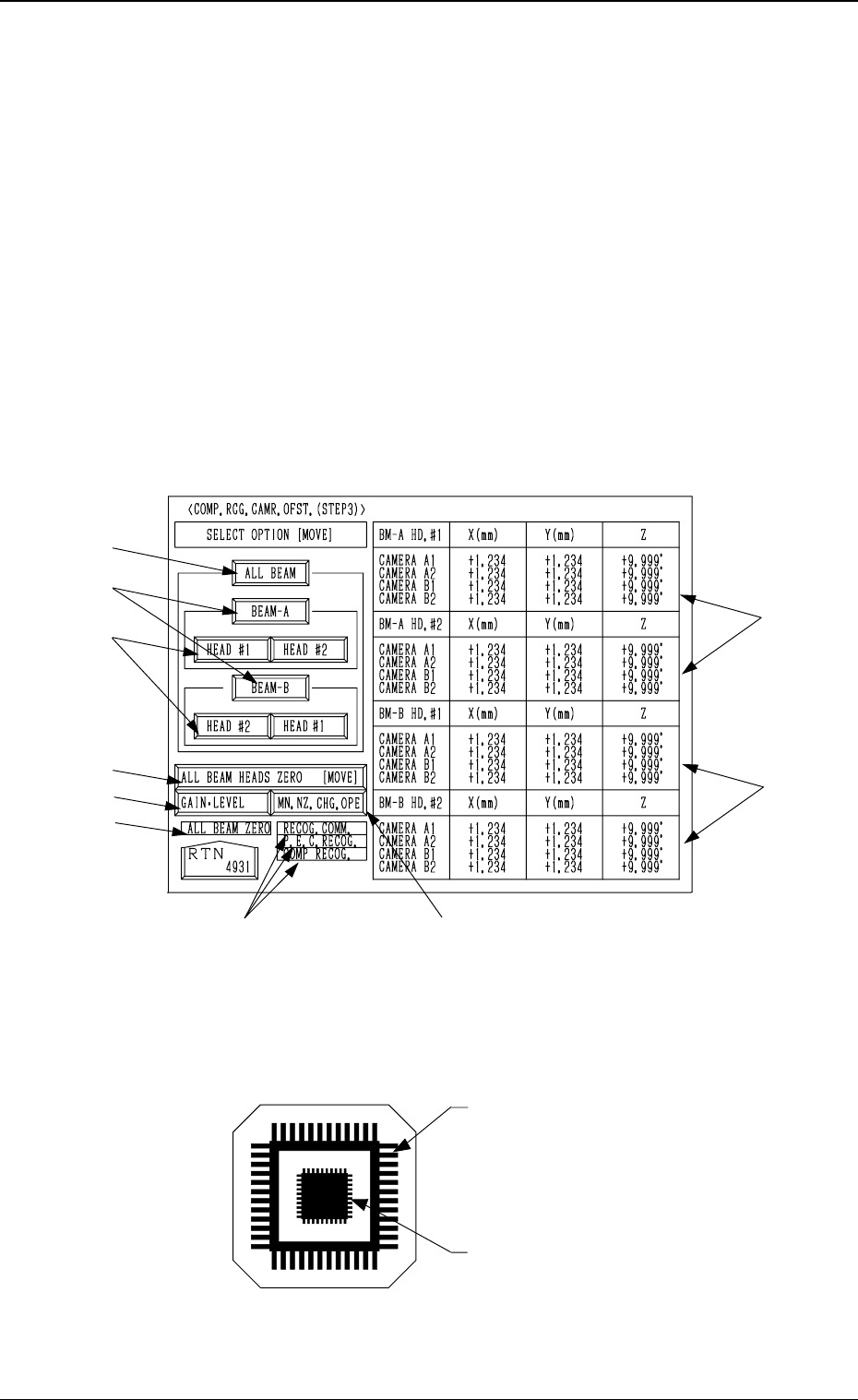
6.3 COMP. RCG. CAMR. OFST. (STEP3) Display
• This display allows teaching the offset data of the component recognition
camera.
The offset values are calculated by recognizing the printed pattern on the jig
component (the teaching plate (component recognition offset jig)) picked
up by a nozzle with both component recognition and P.E.C. recognition cam-
eras.
Note: Follow the teaching procedures in the specified order. Otherwise, some
trouble (such as inaccurate component placement, frequent mechani-
cal errors, etc.) will arise.
When the [COMPONENT RECOG CAMERA OFFSET (STEP-3)] key is
pressed at the “TEACH OFFSET” display, the following display appears on
the screen.
Teaching Plate (Component Recognition Offset Jig: JG-0085)
(Standard Accessory Part)
Note: Handle this fragile jig very carefully.
• Two types of patterns are printed through vapor deposition on the glass for
positional calculation.
*4
*7
*8
*2
*1
*3
*5
*6
*9
*4
9910-001 3-61
6. TEACH OFFSET Display
Fig. 3.39
Fig. 3.40
Pattern to be captured by the
component recognition camera
Pattern to be captured by the
P.E.C. recognition camera
Tg0249-PM-MM
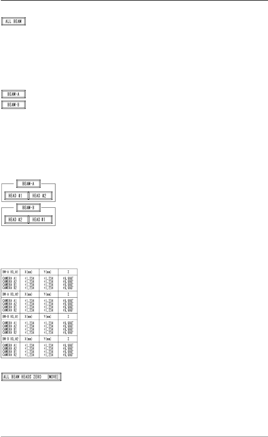
*1 [ALL BEAM] Key
The machine performs the teaching operation of the offset
data for the component recognition cameras installed on
both Beams A and B.
When this key is selected and the [MOVE] button is pressed,
the machine starts the teaching operation.
Note: Before performing the teaching operations, zero
both beams.
*2 [BEAM-A] and [BEAM-B] Keys
The machine performs the teaching operation of the offset
data for the component recognition camera installed on
Beam A or Beam B.
When the [BEAM-A] or the [BEAM-B] key is selected and
the [MOVE] button is pressed, the machine performs the
teaching operation related to the component recognition
camera installed on the selected beam.
Note: Before performing the teaching operations, zero
both beams.
*3 [HEAD #1] and [HEAD #2] Keys in “BEAM-A” Group
Box and [HEAD #1] and [HEAD #2] Keys in “BEAM-B”
Group Box
The machine performs the teaching operation of the offset
data for the component recognition camera.
When one of the above-described keys is selected and the
[MOVE] button is pressed, the machine starts teaching the
offset data related to the selected head #.
Note: Before performing the teaching operations, zero
both beams.
*4 Offset Data
Shown is the offset data of the component recognition cam-
eras installed on Beams A and B.
*5 [ALL BEAM HEADS ZERO [MOVE]] Key
Both Beams A and B are zeroed.
When this key is selected and the [MOVE] button is pressed,
the zeroing operation starts.
9910-001 3-62
6. TEACH OFFSET Display