4OM-1064-001.pdf - 第113页
Tg0249-PM-MM *6 [GAIN LEVEL] Key When this key is pressed, the “GAIN LEVEL” display (Fig. 3.35) appears on the screen. These parameters are used to set amplifications at which the image signals of the image taken by the …
Tg0249-PM-MM
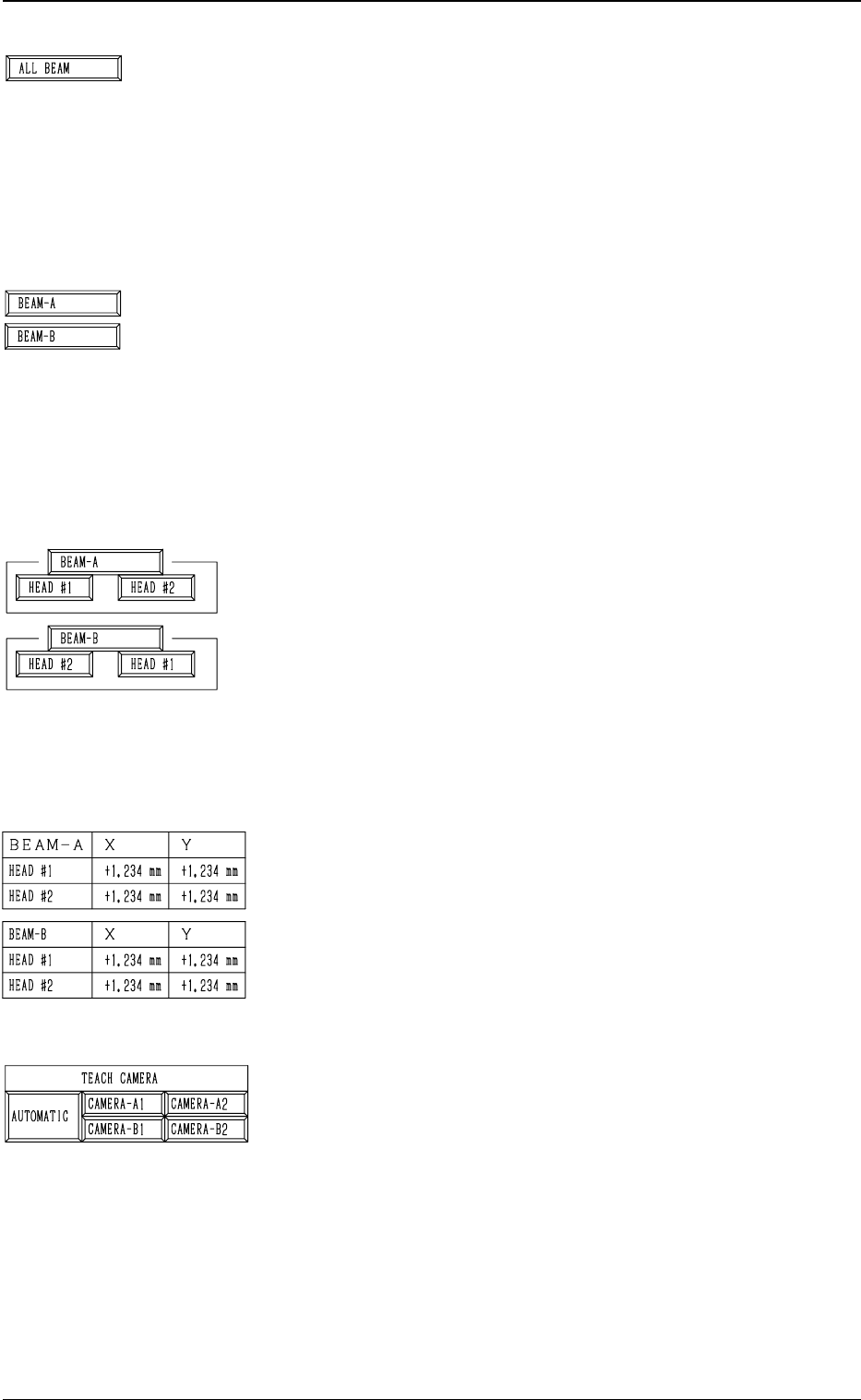
*1 [ALL BEAM] Key
The machine performs the teaching operation of the head
center offset data for both heads on Beams A and B in the
sequential order.
When this key is selected and the [MOVE] button is pressed,
the machine starts the teaching operation.
Note: Before performing the teaching operations, zero
both beams.
*2 [BEAM-A] and [BEAM-B] Keys
The machine performs the teaching operations of the head
center offset data of both heads on Beam A or B.
When the [BEAM-A] or the [BEAM-B] key is selected and
the [MOVE] button is pressed, the machine performs the
teaching operation of the offset data related to the selected
beam.
Note: Before performing the teaching operations, zero
both beams.
*3 [HEAD #1] and [HEAD #2] Keys in “BEAM-A” Group
Box and [HEAD #2] and [HEAD #1] Keys in “BEAM-B”
Group Box
The machine performs the teaching operation of the head
center offset data.
When one of the above-described keys is selected and the
[MOVE] button is pressed, the machine starts teaching the
offset data related to the selected head #.
Note: Before performing the teaching operations, zero
both beams.
*4 Offset Data
Shown is the head center offset data of each head on Beams
A and B.
*5 TEACH CAMERA
A camera can be designated for teaching operations.
“AUTOMATIC”, “CAMERA-A1”, “CAMERA-A2”,
“CAMERA-B1”, or “CAMERA-B2” can be selected.
When “AUTOMATIC” is selected, a camera is automati-
cally selected for teaching operations.
When “CAMERA-A1”, “CAMERA-A2”, “CAMERA-B1”
or “CAMERA-B2” is designated, teaching operation is per-
formed in the designated camera.
0004-002 3-66
6. TEACH OFFSET Display
Tg0249-PM-MM
*6 [GAIN LEVEL] Key
When this key is pressed, the “GAIN
LEVEL” display (Fig.
3.35) appears on the screen.
These parameters are used to set amplifications at which
the image signals of the image taken by the component rec-
ognition camera is converted into the picture information
representing brightness.
Parameters are set as the offset values for camera reference
gain and level.
Normal Fixed Value: ± 0
• When “ENABLE” is set in the “DESIGNATE” data box
at the “GAIN
LEVEL” display, be sure to set param-
eters in the “GAIN” and “LEVEL” data boxes.
The set parameters are used for P.E.C. recognition.
When “DISABLE” is set in the data box, the standard
parameters are set in the “GAIN” and “LEVEL” data
boxes.
• The lower the gain is, the bigger the contrast becomes.
• The lower the level is, the brighter the whole view be-
comes.
Note: Teaching operations are performed through com-
ponent recognition.
Incorrect gain and level parameters lead to the ad-
verse result of teaching operations, causing some
trouble.
*7 [MANUAL NOZZLE CHANGE OPE] Key
When this key is pressed, the “MANUAL NOZZLE
CHANGE OPERATION” display (Fig. 3.38) appears on
the screen.
Designate the head and the nozzle and attach either “MF01”-
, “MF02”- or “MA06”-type nozzle.
Refer to “9. Manual Nozzle Change Operation of Section
4 in Volume 1” for details.
*8 [ALL BEAM HEADS ZERO [MOVE]] Key
Both Beams A and B are zeroed.
When this key is selected and the [MOVE] button is pressed,
the zeroing operation starts.
*9 RECOG. COMM.
When “DISABLE” is set in the “P.E.C.” and “COMPO-
NENT RECOGNITION” data boxes at the “TEST MODE”
display, the background color of “P.E.C. RECOG.” and
“COMP. RECOG.” becomes light red. (No background
color in normal cases).
Note: In this case, the recognition processing is not made
even if the teaching operations are performed.
Therefore, the results of various teaching opera-
tions are not reflected on the offset data.
*10 ALL BEAM ZERO
When all beams are zeroed completely, the background
color turns green. Otherwise, the background has no color.
9910-001 3-67
6. TEACH OFFSET Display

Tg0249-PM-MM
Operation Procedure
• Required Items
Nozzle: 4 pieces of “MF01”, “MF02” or “MA06”
Jig Component: Teaching Plate (Component Recognition Offset Jig)
(Standard Accessory Part)
(1) Set either “MF01”-, “MF02”- or “MA06”-type nozzle in the nozzle
stocker.
(2) Attach the jig component (the teaching plate (component recognition
offset jig)) to the position where the teaching plate is attached.
Note: The printed side of the component recognition offset jig should
face downward.
(3) Check the followings.
• Check that the machine is powered.
• Check that the supply cover is completely closed.
(4) Attach either “MF01”-, “MF02”- or “MA06”-type nozzle to the ob-
jective placement head for teaching at the “MANUAL NOZZLE
CHANGE OPERATION” display.
(5) Designate the camera to be used for teaching.
(6) Select the [ALL BEAM HEADS ZERO [MOVE]] key and press the
[MOVE] button to zero all beam heads.
(7) To specify the gain and level, use the “GAIN
LEVEL” display.
Note: In normal cases, set “DISABLE” in the “DESIGNATE” data
box.
(8) Select the item to be taught and press the [MOVE] button.
The machine starts the teaching operations.
The following series of teaching operations are performed automati-
cally.
The nozzle picks up the teaching plate from the place where the teaching
plate is attached.
↓
The placement head moves to the component recognition camera position.
↓
The jig component is recognized with the component recognition camera.
(Posture at 4 Directions: 0°, 90°, 180°, and 270°)
↓
The teaching plate is returned to the original place (the place where it was
attached)
0004-002 3-68
6. TEACH OFFSET Display
Beam A Side
Teaching Plate
(Component Recognition Offset Jig)
Position of Teaching Plate
Back Light Stage
Magnified View of Teaching Plate Section
Fig. 3.44
Teaching Plate Section
Component Rec-
ognition Camera
Nozzle Stocker
Placement Head
Nozzle Stocker
Placement Head
Beam B Side
Overall Top View
P.E.C. Recogni-
tion Camera
P.E.C. Recognition
Camera