4OM-1064-001.pdf - 第148页
Tg0249-PM-MM *1 [T APE VIB. STICK] Key When this key is pressed, the “PICK-UP LOCA TION (T APE VIB. STICK)” display appears on the screen. Perform the offset teaching operation on the following parameters through manual …
Tg0249-PM-MM
6.9 PICK-UP LOCATION Display
CAUTION
Only a well-trained personnel shall perform
teaching operations.
The component library data and the pattern
program may be modified additionally for the
teaching.
If the teaching operation is not performed cor-
rectly, the pick-up rate may deteriorate.
• The pick-up position of the component at each feeder is taught through
manual alignment operation.
The objective feeders for teaching are those whose pick-up position is reg-
istered in the component data of the current pattern program.
The pick-up rate may be improved after the teaching of the pick-up position
is performed when the pick-up rate is low.
• When the center of the cross lines does not match the center of the compo-
nent on the recognition monitor during teaching operation, perform the teach-
ing operation of the feeder (B) offset data.
• When a component has a groove, a protrusion, etc., and cannot be picked up
at the center without any hindrance, it is possible to perform the teaching
operation on the designation of eccentric pick-up (Chuck Location Adjust-
ment X and Y in Component Library Data).
When the [PICK-UP LOCATION] key is pressed at the “TEACH OFFSET”
display, the following display appears on the screen.
This display can also be opened from the “AUTO OPN. SUB-MENU”
display. (Hierarchical Sequence: “AUTO OPN MODE <PLACEMENT>”
Display → “AUTO OPN. SUB-MENU” Display)
Note: This key can be selected only when the machine is in the “STOP”
mode.
9910-001 3-101
6. TEACH OFFSET Display
Fig. 3.65
*2
*1

Tg0249-PM-MM
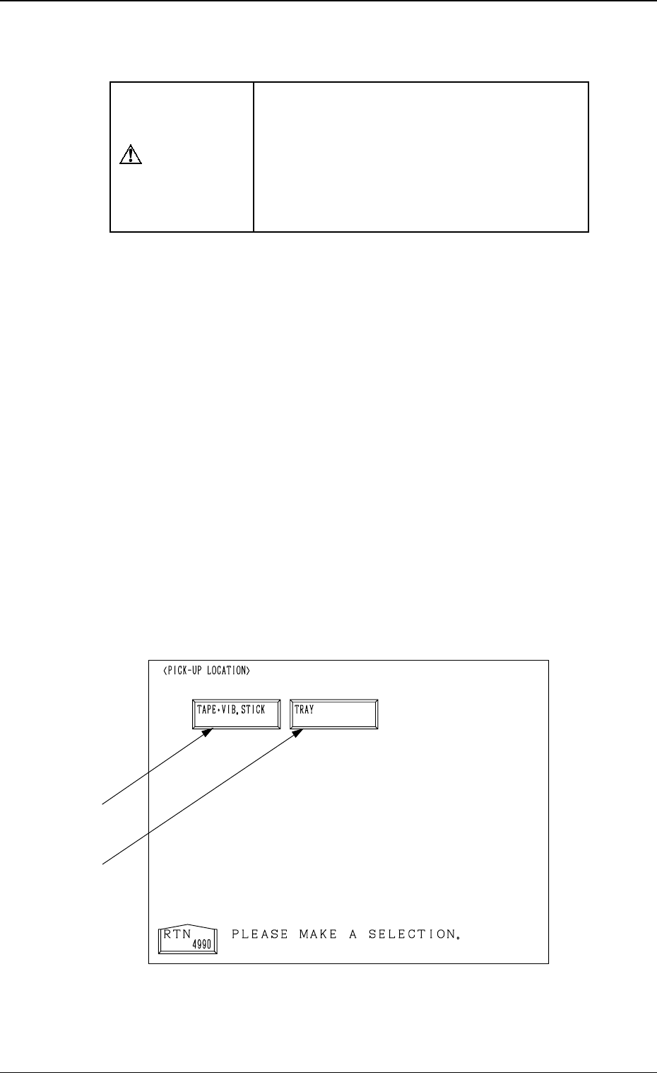
*1 [TAPE VIB. STICK] Key
When this key is pressed, the “PICK-UP LOCATION (TAPE
VIB. STICK)”
display appears on the screen.
Perform the offset teaching operation on the following parameters through
manual alignment operation.
• PICK-UP LOCATION ADJUSTMENT X, Y in the component library
data
• FEEDER (B) OFFSET X and Y
• OFFSET X, Y in the component data
*2 [TRAY] Key (Option)
When this key is pressed, the “PICK-UP LOCATION (TRAY)” display
appears on the screen.
Note: This display cannot be opened while the pallet is being drawn out.
Perform the offset teaching operation on the following parameters through
manual alignment operation.
• PITCH X (mm), Y (mm) and SIDE LG. X (mm), Y (mm) in the compo-
nent library data
• FEEDER (B) OFFSET X and Y
• OFFSET X, Y and PICK-UP LOCATION ADJUSTMENT X, Y
9910-001 3-102
6. TEACH OFFSET Display
Tg0249-PM-MM
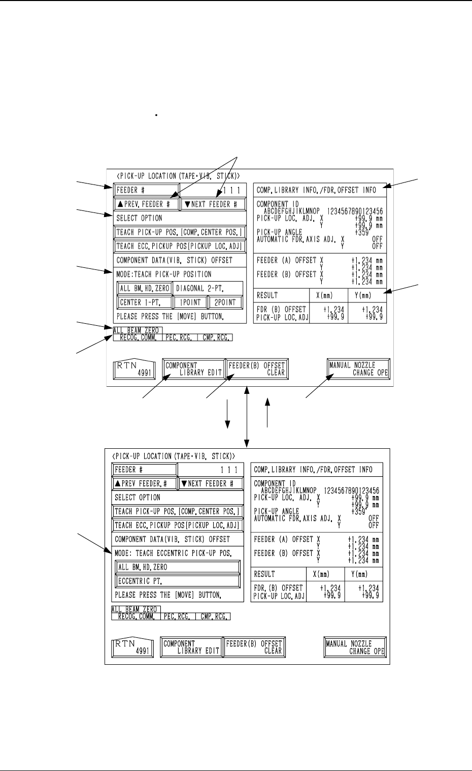
6.10 PICK-UP LOCATION (TAPE·VIB. STICK) Display
• The offset teaching operation is performed on the pick-up location of the
components to be supplied from the tape and vibratory stick feeders.
When the [TAPE
VIB. STICK] key is pressed at the “PICK-UP LOCATION”
display, the following display appears on the screen.
*7
*11
*2
*1
*3
*4
*12
*8 *9
*10
*6
*5
[TEACH ECC. PICKUP POS
[PICKUP LOC. ADJ]] Key
[TEACH PICK-UP POS. [COMP.
CENTER POS.]] Key
9910-001 3-103
6. TEACH OFFSET Display
Fig. 3.66-1
Fig. 3.66-2