4OM-1064-001.pdf - 第150页
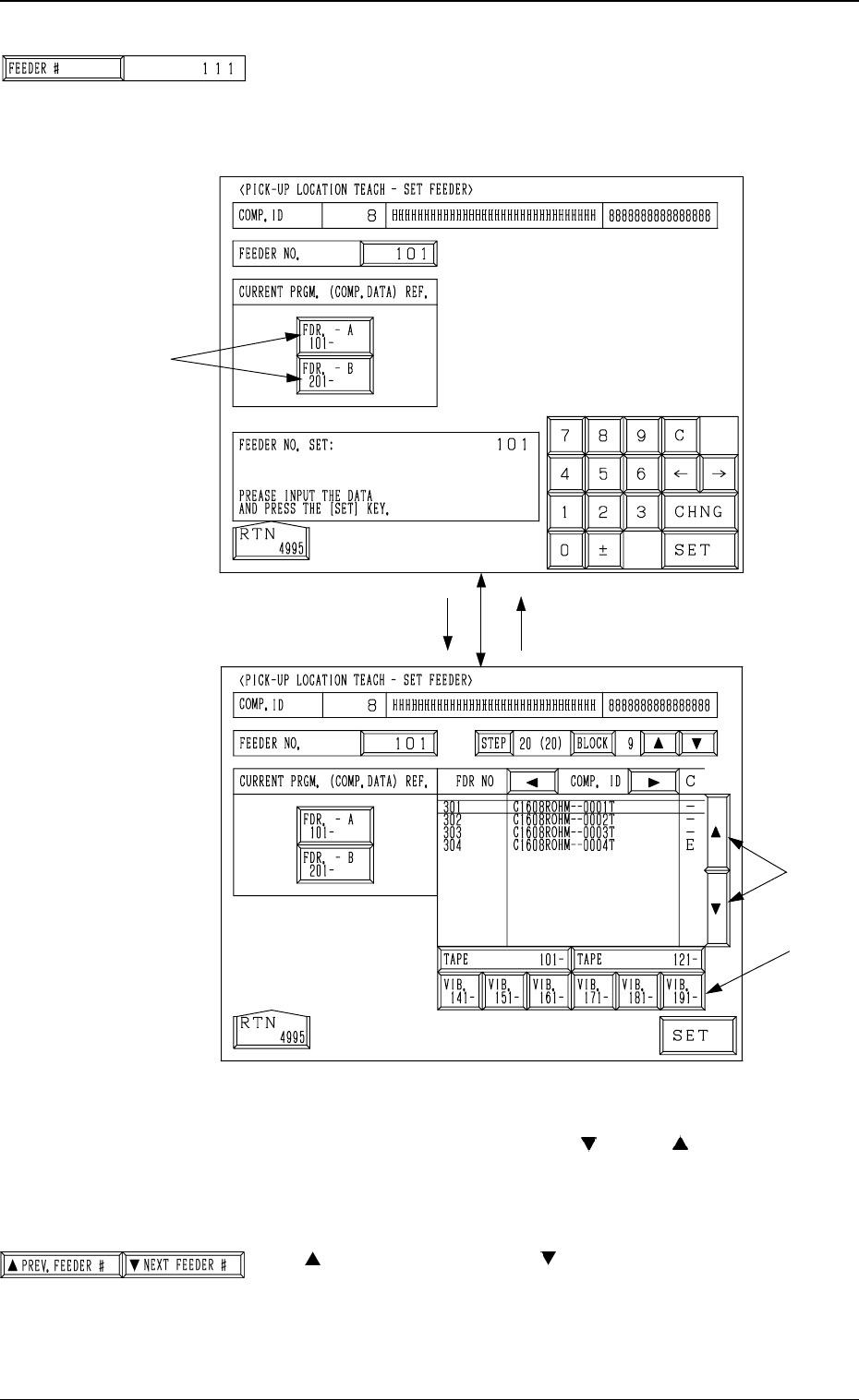
Tg0249-PM-MM *1 [FEEDER #] Key When this key is pressed, the “PICK-UP LOCA TION TEACH - SET FEEDER” display (Fig. 3.67-1) appears on the screen, enabling the setting of the feeder No. whose pick-up location must be taugh…
Tg0249-PM-MM
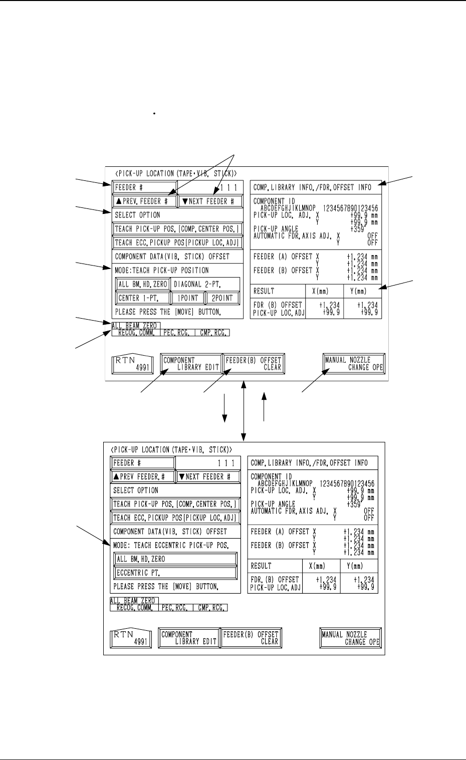
6.10 PICK-UP LOCATION (TAPE·VIB. STICK) Display
• The offset teaching operation is performed on the pick-up location of the
components to be supplied from the tape and vibratory stick feeders.
When the [TAPE
VIB. STICK] key is pressed at the “PICK-UP LOCATION”
display, the following display appears on the screen.
*7
*11
*2
*1
*3
*4
*12
*8 *9
*10
*6
*5
[TEACH ECC. PICKUP POS
[PICKUP LOC. ADJ]] Key
[TEACH PICK-UP POS. [COMP.
CENTER POS.]] Key
9910-001 3-103
6. TEACH OFFSET Display
Fig. 3.66-1
Fig. 3.66-2
Tg0249-PM-MM
*1 [FEEDER #] Key
When this key is pressed, the “PICK-UP LOCATION
TEACH - SET FEEDER” display (Fig. 3.67-1) appears on
the screen, enabling the setting of the feeder No. whose
pick-up location must be taught.
Procedure for Feeder Selection
(1) Select one of the keys A to specify the feeder base.
(2) Select the feeder No., using the [
] or the [ ] key B.
To teach the data related to the vibratory stick feeder,
select one of the keys C to specify the feeder carriage.
(3) Press the [SET] key.
*2 [
PREV. FEEDER #] and [ NEXT FEEDER #] Keys
The feeder Nos. registered in the component data of the
current program are scrolled up or down.
This function automatically skips the feeder Nos. which
are not specified in the current program or the feeder Nos.
for which no components are set in the component data.
[FDR. -A 101- ]
B
C
[101]
Fig. 3.67-1
A
Fig. 3.67-2
0004-002 3-104
6. TEACH OFFSET Display
Tg0249-PM-MM
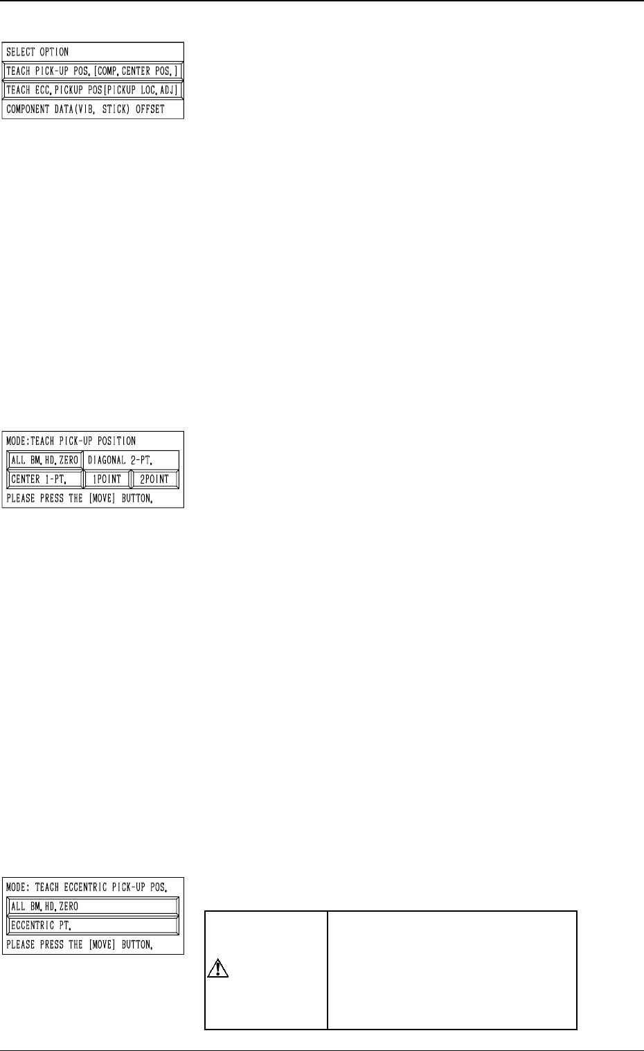
*3 “SELECT OPTION”
[TEACH PICK-UP POS. [COMP. CENTER POS.]] Key
When this key is pressed, the display (Fig. 3.66-1) ap-
pears on the screen.
To teach the center position of the component, use this
function for the “FEEDER (B) OFFSET” teaching.
[TEACH ECC. PICKUP POS [PICKUP LOC. ADJ]] Key
When this key is pressed, the display (Fig. 3.66-2) ap-
pears on the screen.
When a component has a groove, a protrusion, etc., and
cannot be picked up at the center without any hindrance,
use this function for the “PICK-UP LOCATION AD-
JUSTMENT X, Y” teaching.
[COMPONENT DATA (VIB. STICK) OFFSET] Key
When this key is pressed, the display (Fig. 3.75) ap-
pears on the screen.
Use this function to teach “OFFSET X, Y”.
This key can be selected only when the feeder No. se-
lected in *1 is allocated to a vibratory stick feeder.
*4 “MODE: TEACH PICK-UP POSITION”
This is used to additionally modify “FEEDER (B) OFF-
SET X, Y”.
[ALL BM. HD. ZERO] Key
Both Beams A and B are zeroed.
When this key is selected and the [MOVE] button is
pressed, the zeroing operation starts.
[CENTER 1-PT.] Key
When this key is selected and the [MOVE] button is
pressed, the P.E.C. recognition camera moves to the com-
ponent center position (Position of “Design Position +
Feeder (A) Offset + Feeder (B) Offset”) of the pertinent
feeder, making it possible to capture the image. Under
this condition, shift to the trackball operation and per-
form the manual alignment operation.
“DIAGONAL 2-PT.” [1POINT] and [2POINT] Keys
These keys are used to align the component with two
diagonally-located points.
Use this function when the maximum outside dimen-
sions of the component exceed “10 × 10 mm” (when
the whole image of the component cannot be captured
on the recognition monitor).
*5 “MODE: TEACH ECCENTRIC PICK-UP POS.”
“PICK-UP LOCATION ADJUST-
MENT X, Y” in the component li-
brary data is modified additionally.
Incorrect teaching operation will
cause the pick-up rate to deterio-
rate.
6. TEACH OFFSET Display
9910-001 3-105
CAUTION