4OM-1064-001.pdf - 第156页
Tg0249-PM-MM (3) When the [2POINT] key is selected and the [MOVE] button is pressed, the P .E.C. recognition camera moves to the designated feeder No. posi- tion. “ (second point)” appears on the recognition monitor. (4)…
Tg0249-PM-MM
• Trackball Operation
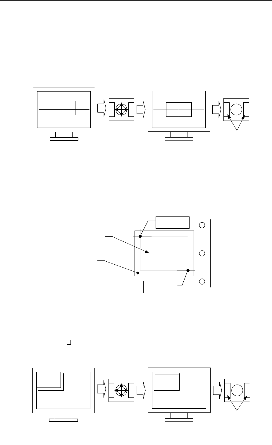
[CENTER 1-PT.] Key
The cross hairs appear on the recognition monitor.
Adjust the cross hairs to the pick-up point, using the trackball.
(1) When the [CENTER 1-PT.] key is selected and the [MOVE] button is
pressed, the P.E.C. recognition camera moves to the designated feeder
No. position.
(2) Manipulate the trackball as shown in Fig. 3.70.
“DIAGONAL 2-PT.”
Specify the two edges of the component to be picked up or the embossed
mounting hole.
Specify the edge two points of the component in embossed.
Or, specify two corners (points) of the embossed mounting hole.
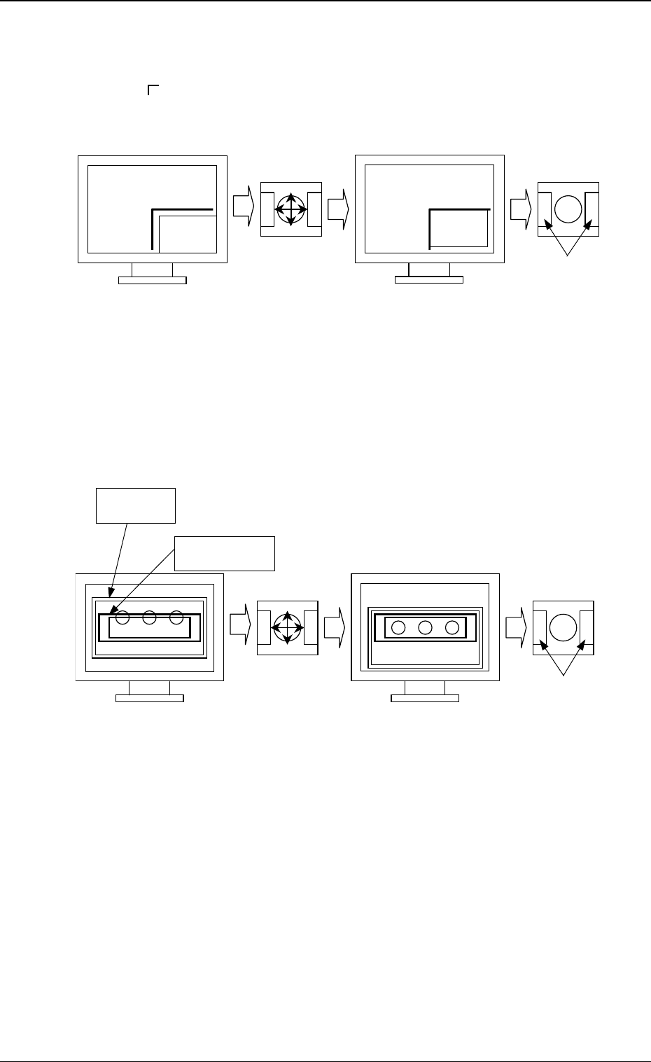
(1) When the [1POINT] key is selected and the [MOVE] button is pressed,
the P.E.C. recognition camera moves to the designated feeder No. posi-
tion.
“ (first point)” appears on the recognition monitor.
(2) Make an alignment with the trackball and press the right and left but-
tons simultaneously.
9910-001 3-109
6. TEACH OFFSET Display
Fig. 3.70
Fig. 3.71
Fig. 3.72
Press the buttons
simultaneously.
Roll the ball for
alignment.
Trackball
Trackball
Crosshairs dislocated from the
pick-up point
Second Point
First Point
Component
Embossed
Mounting Hole
Roll the ball for
alignment.
Trackball
Trackball
Press the buttons
simultaneously.
Tg0249-PM-MM
(3) When the [2POINT] key is selected and the [MOVE] button is pressed,
the P.E.C. recognition camera moves to the designated feeder No. posi-
tion.
“ (second point)” appears on the recognition monitor.
(4) Make an alignment with the trackball and press the right and left buttons
simultaneously.
[TEACH ECC. PICKUP POS [PICKUP LOC. ADJ]] Key
(1) When the [ECCENTRIC PT.] key is selected and the [MOVE] button is
pressed, the P.E.C. recognition camera moves to the designated feeder
No. position.
The graphic of the nozzle appears on the recognition monitor.
(2) Make an alignment with the trackball and press the right and left buttons
simultaneously.
9910-001 3-110
Fig. 3.73
Fig. 3.74
Press the buttons
simultaneously.
Roll the ball
for alignment.
TrackballTrackball
Press the buttons
simultaneously.
Roll the ball
for alignment.
Trackball
Trackball
Nozzle Graphic
Component
Tg0249-PM-MM
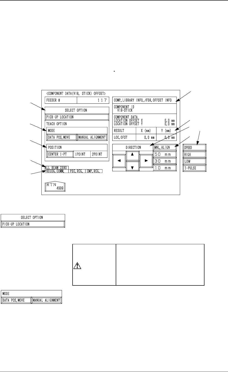
6.11 COMPONENT DATA (VIB. STICK) OFFSET
Display
• This display allows the teaching operations on the pick-up position offset of
the component to be supplied from the vibratory stick feeder.
When the [COMPONENT DATA (VIB. STICK) OFFSET] key is pressed at
the “PICK-UP LOCATION (TAPE
VIB. STICK)” display, the following dis-
play appears on the screen.
*1 “SELECT OPTION” [PICK-UP LOCATION] Key
When this key is selected and the [MOVE] button is pressed,
the machine performs the teaching operation on the com-
ponent data offset.
CAUTION
“OFFSET X (mm), Y (mm)” in the
component data of the pattern pro-
gram is modified additionally.
Incorrect teaching operation will
cause the pick-up rate to deterio-
rate.
*2 “MODE”
[DATA POS. MOVE] Key
When one of the “POSITION” keys *3 is selected and
the [MOVE] button is pressed after this key is selected,
the X/Y beam (center of P.E.C. recognition camera)
moves to the position where the parameters set in the
“X (mm)” and “Y (mm)” data fields of the label “OFF-
SET” in the component library data and the component
data are referred to.
[MANUAL ALIGNMENT] Key
When one of the “POSITION” keys *3 is selected and
the [MOVE] button is pressed after this key is selected,
the trackball operation becomes accessible.
9910-001 3-111
6. TEACH OFFSET Display
*2
*3
*9
*7
*10
*8
*5
*4
*6
Fig. 3.75
*1