4OM-1064-001.pdf - 第160页
Tg0249-PM-MM *5 *7 *6 *8 *2 *9 *3 *4 *10 *1 1 *7 *1 *12 6. TEACH OFFSET Display Fig. 3.76 6.12 PICK-UP LOCA TION (TRA Y) Display (Option) • This display allows the teaching operations on the pick-up position offset of th…

Tg0249-PM-MM
The following three methods are prepared for the component data offset
teaching.
Operation Procedure (Movement of Data Position)
(1) Select the [DATA POS. MOVE] key of “MODE”.
(2) Select the [CENTER 1-PT] key (the [1POINT] key in the case of diago-
nal 2-point alignment) and press the [MOVE] button.
The X/Y beam moves to the position where the parameters set in the “X
(mm)” and “Y (mm)” data fields of the label “OFFSET” in the compo-
nent data are referred to.
(3) In the case of diagonal 2-point alignment, select the [2POINT] key and
press the [MOVE] button.
Manual Alignment Operation Procedure (Trackball Operation)
(1) Select the [MANUAL ALIGNMENT] key of “MODE”.
(2) Select the [CENTER 1-PT] key (the [1POINT] key in the case of diago-
nal 2-point alignment) and press the [MOVE] button.
(3) Manipulate the trackball to perform the manual alignment.
Refer to “6.8.9 Teaching Operation with Trackball” for details.
(4) In the case of diagonal 2-point alignment, select the [2POINT] key and
press the [MOVE] button. Then, manipulate the trackball to perform the
manual alignment.
Operation Procedure (Smooth Manual Alignment)
(1) Select either the [
], the [ ], the [ ], or the [ ] key of “DIRECTION”.
(2) Select the speed by selecting one of the keys under “SPEED”.
(3) The X/Y beam moves in the specified direction at the selected speed
while the [MOVE] button is being pressed.
It stops when the [MOVE] button is released.
Operation Procedure (Inching Movement)
(1) Select either the [
], the [ ], the [ ], or the [ ] key of “DIRECTION”.
(2) Select either the [50 mm], the [30 mm], or the [10 mm] key of “MNL.
ALIGN”.
(3) When the [MOVE] button is pressed, the X/Y beam moves in the speci-
fied direction as far as the specified distance (inching distance).
9910-001 3-113
6. TEACH OFFSET Display
Tg0249-PM-MM
*5
*7
*6
*8
*2
*9
*3
*4
*10
*11
*7
*1
*12
6. TEACH OFFSET Display
Fig. 3.76
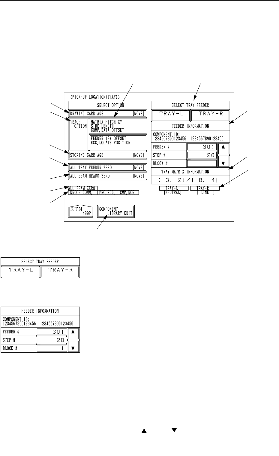
6.12 PICK-UP LOCATION (TRAY) Display (Option)
• This display allows the teaching operations on the pick-up position offset of
the component to be supplied from the multi-layer tray feeder (option).
When the [TRAY] key is pressed at the “PICK-UP LOCATION” display, the
following display appears on the screen.
*1 “SELECT TRAY FEEDER” [TRAY-L] and [TRAY-R]
Keys
Select the multi-layer tray feeder where the components to
be taught are set.
Note: The tray feeder not registered in the component of
the current pattern program cannot be selected.
*2 “FEEDER INFORMATION”
Select the component (FDR NO.) to be taught.
Note: No selection can be made with the pallet being
drawn out.
*a “COMPONENT ID”
Displayed is the component ID related to the
specified feeder No.
*b “FEEDER #”
Displayed is the multi-layer tray feeder which
is selected by “SELECT TRAY FEEDER” in
*1 and has the smallest feeder No. among the
registered ones.
Only the feeder No. registered in the compo-
nent data of the current
pattern program is dis-
played and scrolled up or down by pressing
the
[ ] or the [ ] key on the right side.
Note: When only one feeder No. is regis-
tered, it cannot be scrolled up or down.
9910-001 3-114
Tg0249-PM-MM
*c “STEP #”
When “FEEDER #” in *b is selected, the step
No. where the feeder No. is registered is dis-
played.
When the feeder No. selected in *b is allo-
cated to several steps, the currently displayed
step No. can be changed by pressing the [
] or
the [
] key.
*d “BLOCK #”
When *b and *c are selected, the block No.
where the feeder No. is registered is displayed.
When the identical feeder Nos. are set in sev-
eral blocks in accordance with the feeder and
step Nos. selected in *b and *c, the block No.
can be changed by pressing the [
] or the
[
] key after the key beside “BLOCK #” is
selected.
*3 “TRAY MATRIX INFORMATION” (X, Y)/(X, Y)
Displayed are the coordinates (X, Y) representing from
which tray in the specified block the components must be
picked up first and the matrices (X, Y) specified in the com-
ponent library data.
*4 “TRAY-L” and “TRAY-R”
It is shown which mode “[NEUTRAL], [LINE], or [LO-
CAL]” the right and left multi-layer tray feeders are in and
whether they are zeroed or not.
When the multi-layer tray feeder is zeroed, “” appears.
Note: The condition of the disconnected multi-layer tray
feeder is not shown.
*5 [DRAWING CARRIAGE [MOVE]] Key
When this key is selected and the [MOVE] button is pressed,
the pallet related to the specified feeder No. and step is
drawn out.
*6 [STORING CARRIAGE [MOVE]] Key
When this key is selected and the [MOVE] button is pressed,
the drawn pallet is stored in the magazine.
*7 “TEACH OPTION”
[MATRIX PITCH XY SIDE LENGTH COMP. DATA
OFFSET] Key
When this key is pressed, the display (Fig. 3.77) ap-
pears on the screen, enabling the teaching operation of
the matrix pitch X and Y, the side length, and the com-
ponent data offset.
[FEEDER (B) OFFSET ECC. LOCATE POSITION]
Key
When this key is pressed, the display (Fig. 3.80) ap-
pears on the screen, enabling the teaching operation of
the feeder (B) offset and the eccentric pick-up position.
*8 [ALL TRAY FEEDER ZERO [MOVE]] Key
This key is used to zero all multi-layer tray feeders..
When this key is selected and the [MOVE] button is pressed,
the zeroing operation starts.
*9 [ALL BEAM HEADS ZERO] Key
This key is used to zero both Beams A and B.
When this key is selected and the [MOVE] button is pressed,
the zeroing operation starts.
6. TEACH OFFSET Display
9910-001 3-115