4OM-1064-001.pdf - 第164页
Tg0249-PM-MM [PICK-UP FIRST POS.] Key When this key is pressed, the teaching operation is per- formed on the position where the first component should be taken out from the tray . While the “SIDE LENGTH” parameters (X an…
Tg0249-PM-MM
• This display allows the teaching operation on the matrix pitch X and Y, the side length,
and the component data offset of the tray.
Described in this session is mainly how to teach the component library data items. The next
session “Teaching Operation of Feeder (B) Offset” describes how to teach the pick-up posi-
tion at each step when the same types of components (the same library data) are used in
several steps of the magazine.
This teaching operation is performed on each component library data.
Note: Before performing the teaching operation, be sure to confirm that correct param-
eters are set in the “X” and “Y” data boxes of the label “MATRIX” in the compo-
nent library data of the pertinent tray.
If incorrect parameters are set, the pitch data cannot be calculated correctly.
When the [MATRIX PITCH XY SIDE LENGTH COMP. DATA OFFSET] key is pressed
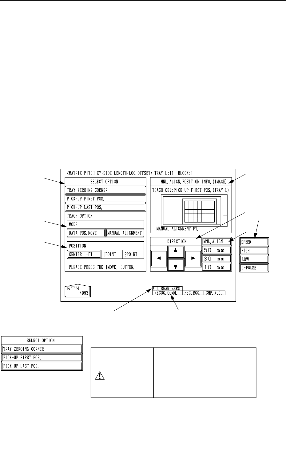
at the “PICK-UP LOCATION (TRAY)” display, the following display appears on the screen.
Note: The graphic looks different when the recognition monitor is installed on the Beam
A side (option).
*1 “SELECT OPTION”
CAUTION
“TRAY DATA” in the component
library data is modified addition-
ally.
Incorrect teaching operation will
cause an error in component
picks.
[TRAY ZEROING CORNER] Key
When this key is pressed, the teaching operation is per-
formed on the tray zeroing corner.
The teaching operation is performed on the tray zeroing
corner through manual alignment to calculate the tray
positional offset (“X (mm)” and “Y (mm)” of “OFF-
SET” in the component data (“Tray Steps Information”).
*8 *9
9910-001 3-117
6. TEACH OFFSET Display
*1
*2
*3
*7
*5
*4
*6
Fig. 3.77
6.12.1 MATRIX PITCH XY·SIDE LENGTH·LOC. OFFSET
Display (Option)
Tg0249-PM-MM
[PICK-UP FIRST POS.] Key
When this key is pressed, the teaching operation is per-
formed on the position where the first component should
be taken out from the tray.
While the “SIDE LENGTH” parameters (X and Y) in
“TRAY DATA” are calculated, the first data for pitch
calculation is extracted.
[PICK-UP LAST POS.] Key
When this key is pressed, the teaching operation is per-
formed on the position where the last component should
be taken out from the tray.
This function is used to extract the second data for pitch
calculation. The “PITCH (CALC.)” parameters (X and
Y) in the component data are calculated in combination
with the previously calculated first data (takeout posi-
tion).
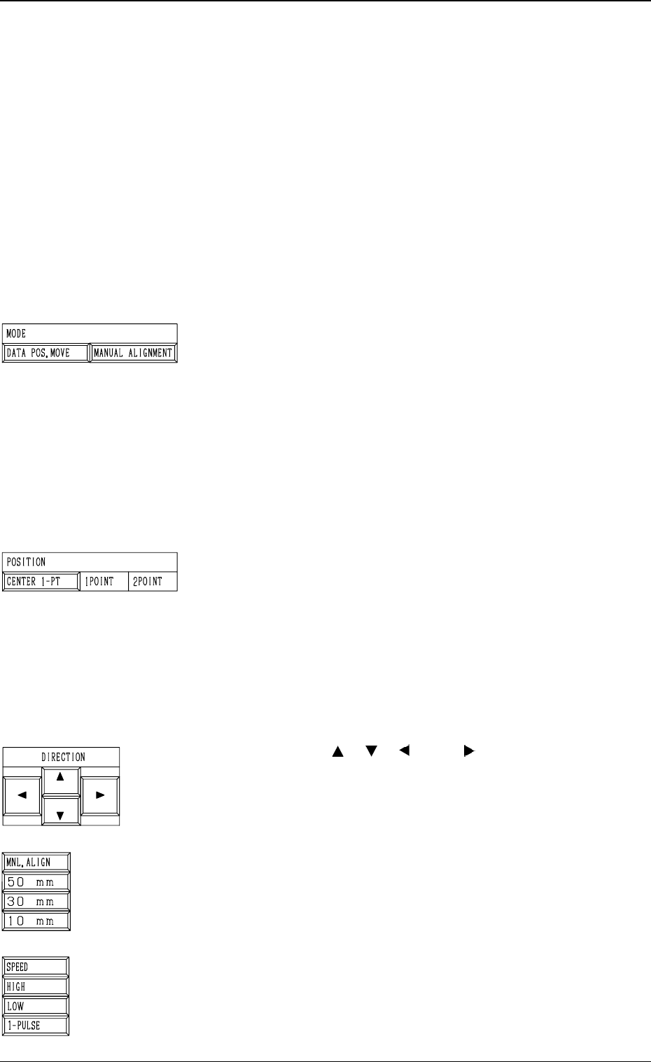
*2 “MODE”
[DATA POS. MOVE] Key
When one of the “POSITION” keys *3 is selected and
the [MOVE] button is pressed after this key is selected,
the X/Y beam (center of P.E.C. recognition camera)
moves to the position where the parameters set in the
“X (mm)” and “Y (mm)” data fields of the label “OFF-
SET” in the component library data and the step data
are referred to.
[MANUAL ALIGNMENT] Key
When one of the “POSITION” keys *3 is selected and
the [MOVE] button is pressed after this key is selected,
the trackball operation becomes accessible.
*3 “POSITION”
[CENTER 1-PT] Key
When this key is pressed, the X/Y beam moves to the
center of the component.
[1POINT] and [2POINT] Keys
These keys are used to align the component with two
diagonally-located points.
When the maximum outside dimensions of the compo-
nent exceeds “10 × 10 mm”, use these keys.
Note: This function cannot be used when the [TRAY
ZEROING CORNER] key is selected in *1.
*4 “DIRECTION” [
], [ ], [ ], and [ ] Keys
Use these keys to specify the direction in which the X/Y
beam is manually aligned.
*5 [MNL. ALIGN], [10 mm], [30 mm], and [50 mm] Keys
Use these keys to select the distance by which the X/Y
beam is manually aligned.
When the [MNL. ALIGN] key is pressed, the [SPEED] and
the related keys appear in place.
*6 [SPEED], [HIGH], [LOW], and [1-PULSE] Keys
Use these keys to specify the speed at which the X/Y beam
is manually aligned.
When the [SPEED] key is pressed, the [MNL. ALIGN] and
the related keys appear in place.
0004-002 3-118
6. TEACH OFFSET Display
Tg0249-PM-MM
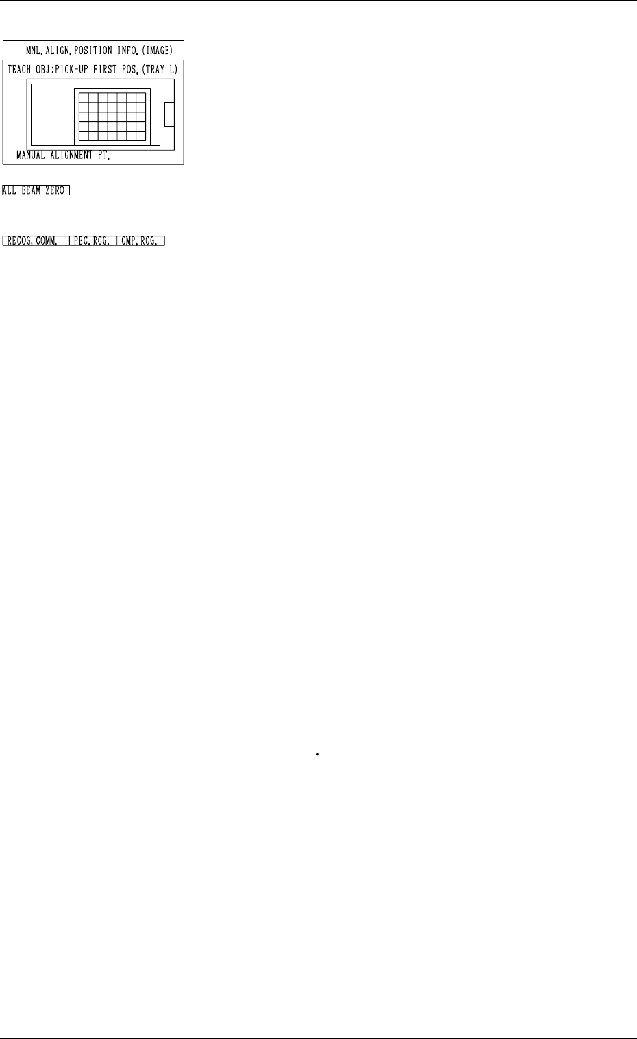
*7 “MNL. ALIGN. POSITION INFO. (IMAGE)”
Displayed is the image of the manually aligned position.
The red cross indicates the manually aligned position.
*8 “ALL BEAM ZERO”
When all beams are zeroed completely, the background turns
green. Otherwise, the background has no color.
*9 “RECOG. COMM.”
When “DISABLE” is set in the “P.E.C.” and “COMPO-
NENT RECOGNITION” data boxes at the “TEST MODE”
display, the background color of “P.E.C. RECOG.” and
“COMP. RECOG.” becomes light red. (No background
color in normal cases)
Operation Procedure
Note: Before performing the teaching operation, be sure to
confirm that correct parameters are set in the “X” and
“Y” data boxes of the label “MATRIX” in the compo-
nent library data of the pertinent tray.
If incorrect parameters are set, the pitch data cannot
be calculated correctly.
(1) Confirm that “ALL BEAM ZERO” is displayed.
(2) Select the [TRAY ZEROING CORNER] key.
(3) Select the [CENTER 1-PT] key.
(4) Select the [DATA POS. MOVE] key.
The P.E.C. recognition camera moves to the specified po-
sition.
(5) Confirm that the origin position of the tray (tray corner)
is on the recognition monitor.
When the origin position of the tray is not displayed, ad-
just it with one of the “MNL. ALIGN” or the “SPEED”
keys.
(6) Select the [MANUAL ALIGNMENT] key and press the
[MOVE] button.
Proceed to the trackball operation and perform the manual
alignment.
Refer to “Trackball Operation in 6.10 PICK-UP LOCA-
TION (TAPE
VIB. STICK) Display” for details.
(7) Select the [PICK-UP FIRST POS.] Key.
(8) Select one of the “POSITION” keys and then the [DATA
POS. MOVE] key.
(9) Confirm that the first component in the tray matrix is
displayed on the recognition monitor.
Otherwise, adjust it with one of the “MNL. ALIGN” or
the “SPEED” keys.
(10) Select the [MANUAL ALIGNMENT] key and press the
[MOVE] button. Proceed to the trackball operation and
perform the manual alignment.
(11) Select the [PICK-UP LAST POS.] key.
Follow the procedure similar to “PICK-UP FIRST POS.”
and perform the teaching operation.
0004-002 3-119
6. TEACH OFFSET Display