4OM-1064-001.pdf - 第167页
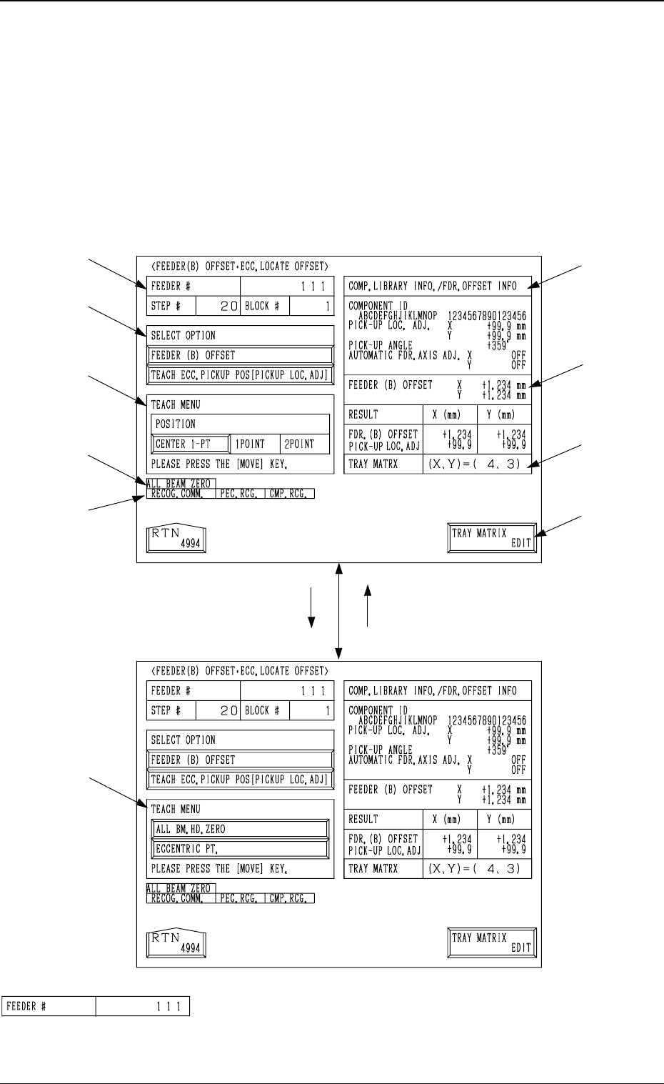
Tg0249-PM-MM 6.12.2 FEEDER (B) OFFSET • • • • • ECC. LOCA TE OFFSET Display (Option) • This display allows the teaching operation on the feeder (B) offset and ec- centric pick-up location of the multi-layer tray feeder (…
Tg0249-PM-MM
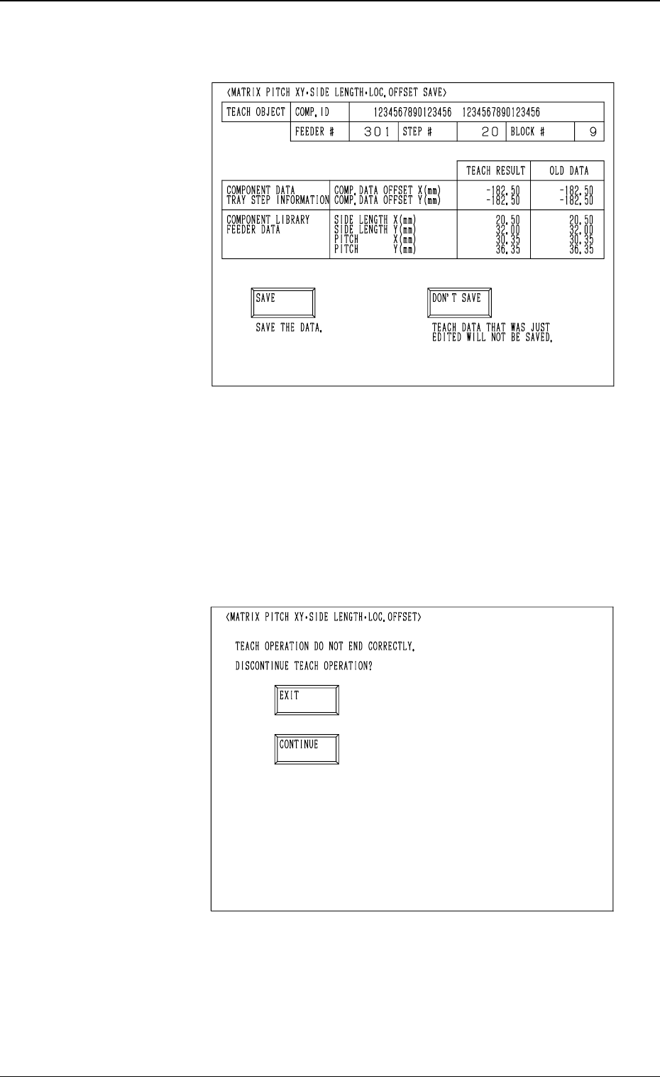
(12) When the teaching operation on the three items is com-
pleted, the following display appears on the screen.
(13) Check the data and determine whether it should be saved
or not.
• When the [SAVE] key is selected, the data is saved
and the display (Fig. 3.76) appears on the screen.
• When the [DON’T SAVE] key is selected, the data is
not saved and the display (Fig. 3.76) appears on the
screen.
• When the teaching operation on the three items is not com-
pleted and the [RTN] key is pressed, the following display
appears on the screen.
Enabling the operator to decide whether or not the teaching
operation should be interrupted.
• When the [EXIT] key is selected, the results of the teach-
ing operation are not reflected and the display (Fig. 3.76)
appears on the screen.
• When the [CONTINUE] key is selected, the display (Fig.
3.77) appears on the screen, enabling the operator to con-
tinue the teaching operation.
0004-002 3-120
6. TEACH OFFSET Display
Fig. 3.78
Fig. 3.79
Tg0249-PM-MM
6.12.2 FEEDER (B) OFFSET
••
••
•
ECC. LOCATE OFFSET
Display (Option)
• This display allows the teaching operation on the feeder (B) offset and ec-
centric pick-up location of the multi-layer tray feeder (option).
When the [FEEDER (B) OFFSET ECC. LOCATE POSITION] key is pressed
at the “PICK-UP LOCATION (TRAY)” display, the following display appears
on the screen.
*1 “FEEDER #”
Shown is the feeder No. which was specified at the display
(Fig. 3.76).
[TEACH ECC. PICKUP POS
[PICKUP LOC. ADJ]] Key
[FEEDER (B) OFFSET] Key
*1
*2
*3
*9
*10
*4
*5
*6
*7
*8
9910-001 3-121
6. TEACH OFFSET Display
Fig. 3.80-1
Fig. 3.80-2
Tg0249-PM-MM
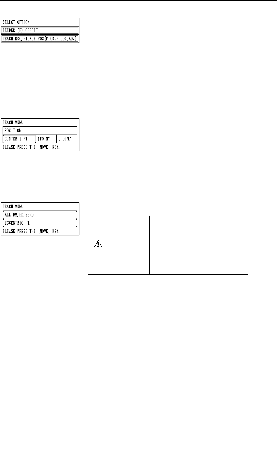
*2 “SELECT OPTION”
[FEEDER (B) OFFSET] Key
When the display (Fig. 3.80-2) is active and this key is
pressed, the display (Fig. 3.80-1) appears on the screen.
Use this function to perform the teaching operation on
the component center position.
[TEACH ECC. PICKUP POS [PICKUP LOC. ADJ]] Key
When the display (Fig. 3.80-1) is active and this key is
pressed, the display (Fig. 3.80-2) appears on the screen.
Use this function when a component has a groove, a
protrusion, etc., and cannot be picked up at the center
without any hindrance.
*3 “TEACH MENU”
“FEEDER (B) OFFSET (X, Y)” is modified additionally.
[CENTER 1-PT.] Key
When this key is pressed, the X/Y beam moves to the
center of the component.
“1POINT” and “2POINT”
These labels are used to align the component with two
diagonally-located points.
When the maximum outside dimensions of the compo-
nent exceeds “10 × 10 mm”, use these keys.
*4 “TEACH MENU”
CAUTION
“PICK-UP LOCATION AD-
JUSTMENT X, Y” in the com-
ponent library data is modified
additionally.
Incorrect teaching operation will
cause the pick-up rate to dete-
riorate.
[ALL BM. HD. ZERO] Key
This key is used to zero both Beams A and B.
When this key is selected and the [MOVE] button is
pressed, the zeroing operation starts.
[ECCENTRIC PT.] Key
When this key is selected and the [MOVE] button is
pressed, the P.E.C. recognition camera moves to the des-
ignated pick-up location correction position based on
the component center position (Position of “Design Po-
sition + Feeder (A) Offset + Feeder (B) Offset”) of the
pertinent feeder, making it possible to capture the im-
age.
Under this condition, shift to the trackball operation and
perform the manual alignment operation.
Note: It is necessary to correctly teach the component
center position before the eccentric position is
adjusted.
9910-001 3-122
6. TEACH OFFSET Display