4OM-1064-001.pdf - 第185页
Tg0249-PM-MM 7.2.1 SET TEST ID Display When the [SET TEST ID] key is pressed at the “COMPONENT RECOG. TEST” display , the following display appears on the screen. [TEST ID LIST (9/100)] Key When the [TEST ID LIST (XXX/…
Tg0249-PM-MM
7. DEVICE TEST Display
9910-001 3-138
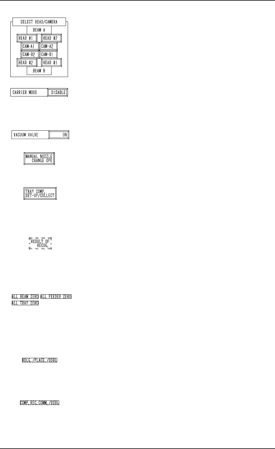
*4 “SELECT HEAD/CAMERA”
The keys in this group box can be used to select the head to
take out components and the component recognition cam-
era to capture an image.
Notes: (a) After the feeder is set, the head which can be
selected is limited.
(b) The head and camera to be bypassed are dis
played in red, indicating that they cannot be
selected.
*5 “CARRIER MODE”
It can be determined whether or not the component feeding
operation of the feeder and the supply operation of the multi-
layer tray feeder must be implemented.
“ENABLE” or “DISABLE” can be selected.
*6 “VACUUM VALVE”
The vacuum for the nozzle can be turned ON or OFF.
*7 [MANUAL NOZZLE CHANGE OPE] Key
When this key is pressed, the “MANUAL NOZZLE
CHANGE OPERATION” display appears on the screen,
enabling the operator to attach or store the nozzle.
*8 [TRAY COMP. SET-UP/COLLECT] Key (Option)
When this key is pressed, the “COMPONENT RECOG.
TEST - TRAY COMPONENT SUPPLY/STORAGE” dis-
play appears on the screen, enabling the operator to draw
out or store the pallet drawing and change the tray pick-up
matrix.
*9 [RESULT OF RECOG.] Key
When this key is pressed, the “RESULT OF COMPONENT
RECOGNITION” display appears on the screen, enabling
the operator to check the results of the component recogni-
tion test.
Note: This key appears after the component recognition
test is performed.
*10 “Set Condition”
The background color becomes green when the set-up op-
erations of “ALL BEAM ZERO”, “ALL FEEDER
ZERO”, and “ALL TRAY ZERO” are completed. Other-
wise, the backgrounds have no color.
Note: When the recognition test is performed with each
section not set up, it may not be implemented cor-
rectly.
*11 “HDLG./PLACE./DSBL”
This appears when “DISABLE” is set in the “HAN-
DLING/PLACEMENT MODE” data box at the “TEST
MODE” display.
The operation is performed normally.
*12 “COMP. REC. COMM./DSBL”
This appears when “DISABLE” is set in the “COMPO-
NENT RECOGNITION” data box at the “TEST MODE”
display.
(Background Color: Light Red)
The recognition processing is made normally.
Tg0249-PM-MM
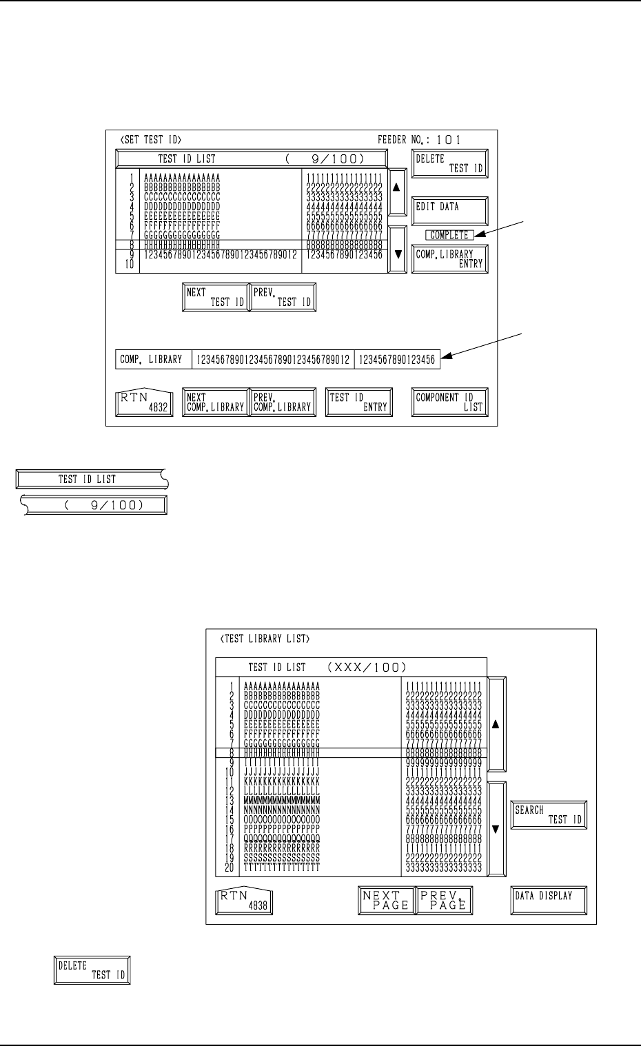
7.2.1 SET TEST ID Display
When the [SET TEST ID] key is pressed at the “COMPONENT RECOG.
TEST” display, the following display appears on the screen.
[TEST ID LIST (9/100)] Key
When the [TEST ID LIST (XXX/100)] key is pressed at
the “SET TEST ID” display, the following display appears
on the screen.
The [SEARCH TEST ID] key is provided to easily locate
the test ID of the data to be corrected.
The [DATA DISPLAY] key is also provided to display the
contents of the test ID data.
[DELETE TEST ID] Key
When this key is pressed, the test ID data (one of the IDs
under the [TEST ID LIST (XXX/100)] key) at the line cur-
sor is deleted.
7. DEVICE TEST Display
0004-002 3-139
B
A
Fig. 3.92-1
Fig. 3.92-2
Tg0249-PM-MM
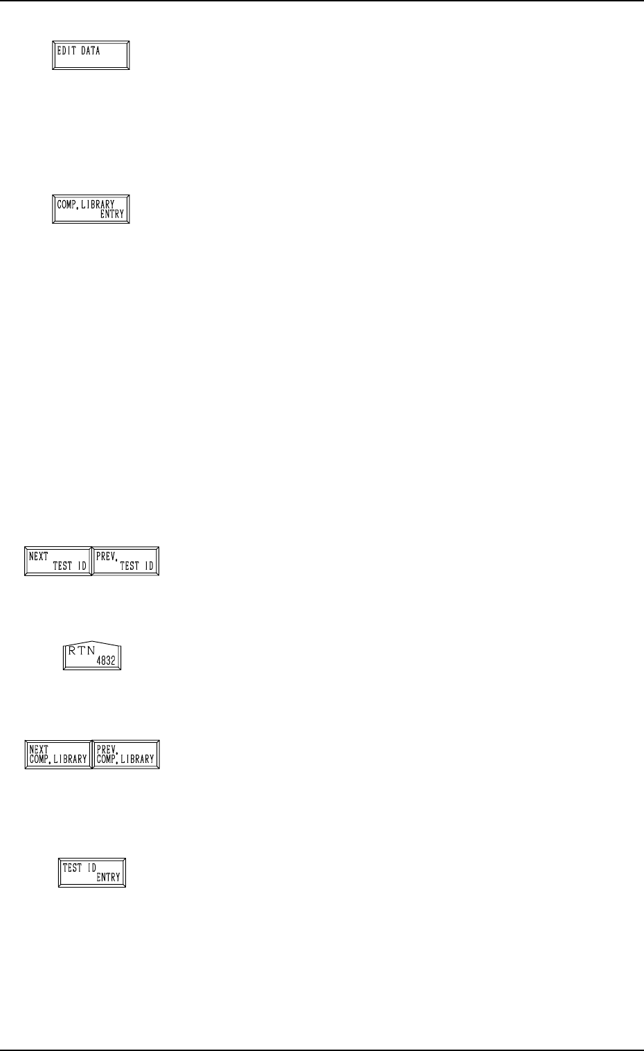
[EDIT DATA] Key
When this key is pressed, a display appears, enabling the
editing of the data which corresponds to the test compo-
nent ID at the line cursor position in the list box under the
[TEST ID LIST (XXX/100)] key.
Refer to the “COMPONENT LIBRARY” for details.
[COMP. LIBRARY ENTRY] Key
When this key is pressed, the data corresponding to the test
ID at the cursor position in the list box under the [TEST ID
LIST (XXX/100)] key can be registered in the component
library with a component ID.
When the registration is completed normally, it is indicated
at B in Fig. 3.92-1 for 5 seconds.
When the same component ID is already registered, the
“DATA SAVE MODE” display appears, enabling the op-
erator to select one of the option keys ([SAVE] and [DON’T
SAVE] key).
Note: As test IDs are protected by the password in the
same level (password available areas) as that of the
component library data (Saving and Deleting), they
may not be registered.
Refer to “3. Management of Password of Section
4” for details.
[NEXT TEST ID] and [PREV. TEST ID] Keys
When the [NEXT TEST ID] key is pressed, another list of
test IDs appears in the list box. Pressing the [PREV. TEST
ID] key lists up the previous test IDs.
[RTN] Key
When this key is pressed, the test ID data at the line cursor
position in the list box is set as the component ID objective
in data correction.
[NEXT COMP. LIBRARY] and [PREV. COMP. LI-
BRARY] Keys
When the [NEXT COMP. LIBRARY] or the [PREV. COMP.
LIBRARY] key is pressed, the next or the previous library
data appears in the “COMP. LIBRARY” text boxes *A.
[TEST ID ENTRY] Key
When this key is pressed, the component IDs (component
library data) in the text box A in Fig.3.92-1are registered
as test ID data.
Ref.: Up to 100 pieces of test ID data can be registered.
7. DEVICE TEST Display
0004-002 3-140