4OM-1064-001.pdf - 第20页
Tg0249-PM-MM 5. Weekly Maintenance T able 1.5 5. Weekly Maintenance 0004-002 1-10 Fig. 1.1 1 Air Regulator Beam A Side Drain Cleaning Drain water according to the following procedure. (1) Place a container under the drai…
Tg0249-PM-MM
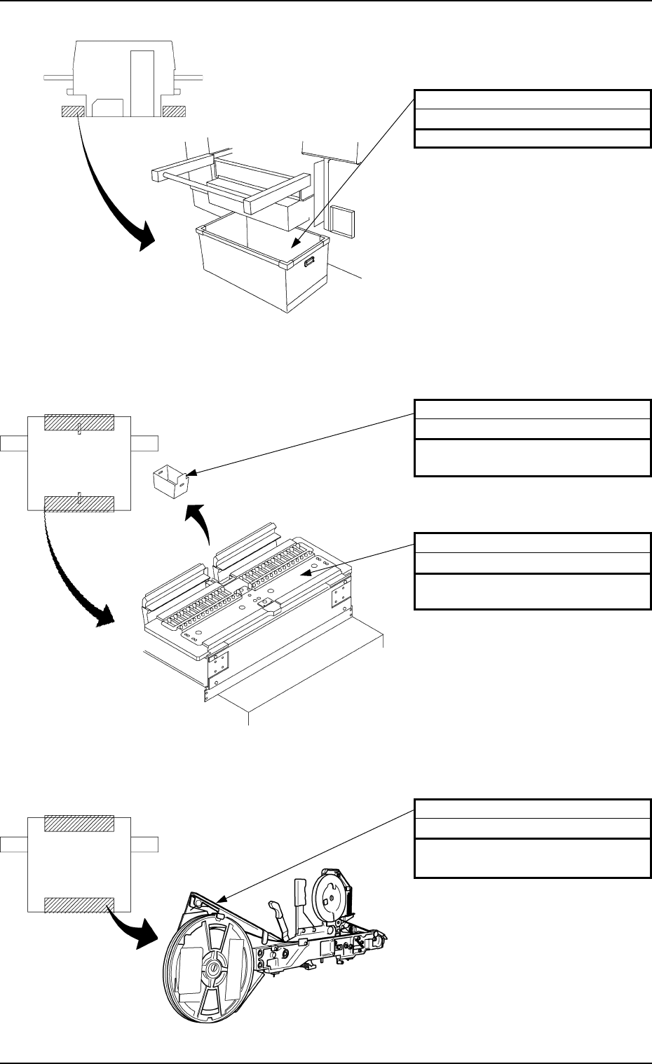
Fig. 1.8 Scrap Box
Fig. 1.9 Feeder Base and Scrap Box
Fig. 1.10 Component Supply Section (Feeder)
4. Daily Maintenance
1-9
Component Discharge Box
Abandonment
Remove the components accumu-
lated in the box.
Whole Body of Tape Feeder
Checking and Cleaning
Check it for damage or dirt. Clean
the tape feeder if it is dirty.
Upper Surface of Feeder Base
Cleaning
Remove the waste and foreign mate-
rial.
Beam B Side Beam A Side
Beam B Side
Beam A Side
Beam A Side
Beam B Side
Empty Tape Box
Abandonment
Remove the empty tapes.
0004-002
Tg0249-PM-MM
5. Weekly Maintenance
Table 1.5
5. Weekly Maintenance
0004-002 1-10
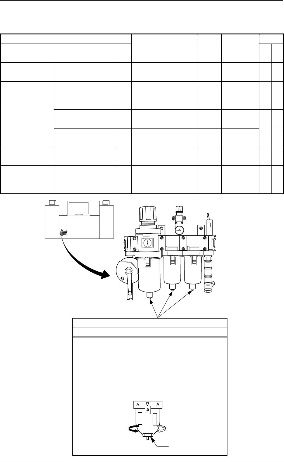
Fig. 1.11 Air Regulator
Beam A Side
Drain
Cleaning
Drain water according to the following procedure.
(1) Place a container under the drain outlet.
(2) Turn slowly the cap on the bottom of the outer case
of each air filter in the direction of Arrow A.
Note: Take the greatest care because dirty water will
splash out from the outlet if the cap is turned
too much.
Ca
p
A
Maintenance Spots Check
Name
Fig.
No.
Description Grease
Cleaning
Tools,
Nozzles, etc.
Air Regulator Drain 1.11 Cleaning Container,
etc.
Component
Recognition
Section
Protective Glass of
the Component
Recognition Camera
1.12 Cleaning Rag, Air
Blow for
Camera
Upper Surface of
Fiducial Mark
1.12 Cleaning Rag
Component Discharge
Box
1.12 Abandonment
PCB Positioning
Section
Upper Surface of
Backup Table
1.13 Cleaning Vacuum
Cleaner
Component
Supply Section
(Feeder)
Component Pick-Up
Position of Tape
Feeder
1.14 Cleaning
Tg0249-PM-MM
5. Weekly Maintenance
9910-001 1-11
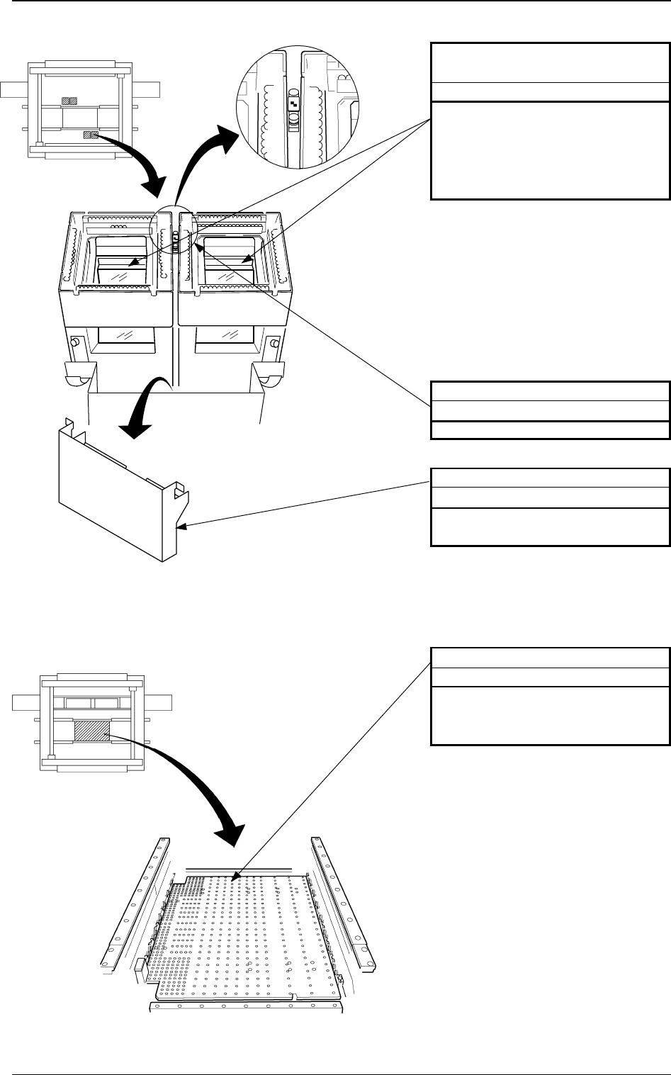
Fig. 1.13 PCB Positioning Section
Upper Surface of Fiducial Mark
Cleaning
Remove dirt and dust using a rag.
Component Discharge Box
Abandonment
Remove the components accumu-
lated in the box.
Protective Glass of the Compo-
nent Recognition Camera
Cleaning
Drop dirt and dust into the compo-
nent discharge box using the air blow
for the camera. If the protective glass
is dirty with grease, remove it using
a rag.
Fig. 1.12 Component Recognition Section
Beam A Side
Beam B Side
Beam A Side
Beam B Side
PCB Positioning Section
Cleaning
Clean dirt and dust on the upper sur-
face of the PCB backup table using a
vacuum cleaner.