4OM-1064-001.pdf - 第224页
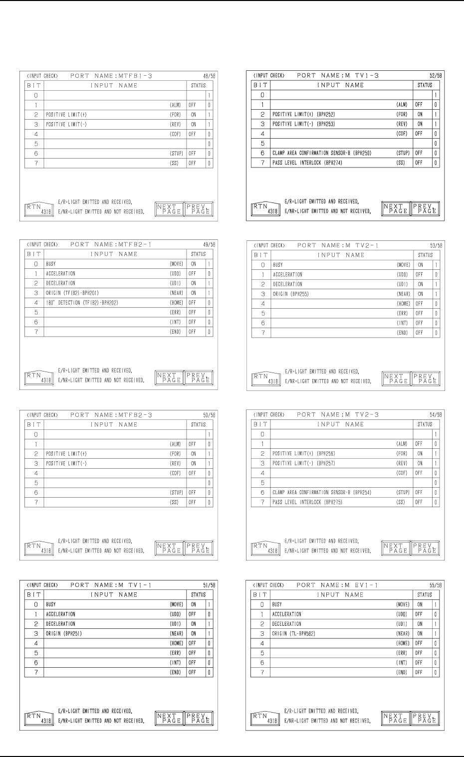
Tg0249-PM-MM 8. DEVICE CHECK Display 0004-002 3-178 Note: The -marked functions are optional.
Tg0249-PM-MM
Note: The -marked functions are optional.
8. DEVICE CHECK Display
0004-002 3-177
Tg0249-PM-MM
8. DEVICE CHECK Display
0004-002 3-178
Note: The -marked functions are optional.
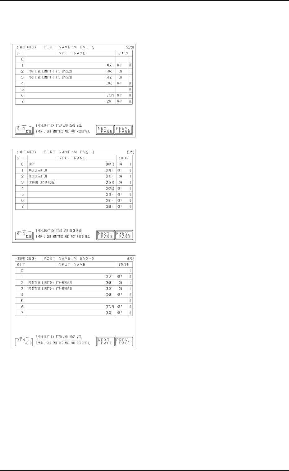
9910-001 Tg0249-PM-MM
8. DEVICE CHECK Display
3-179
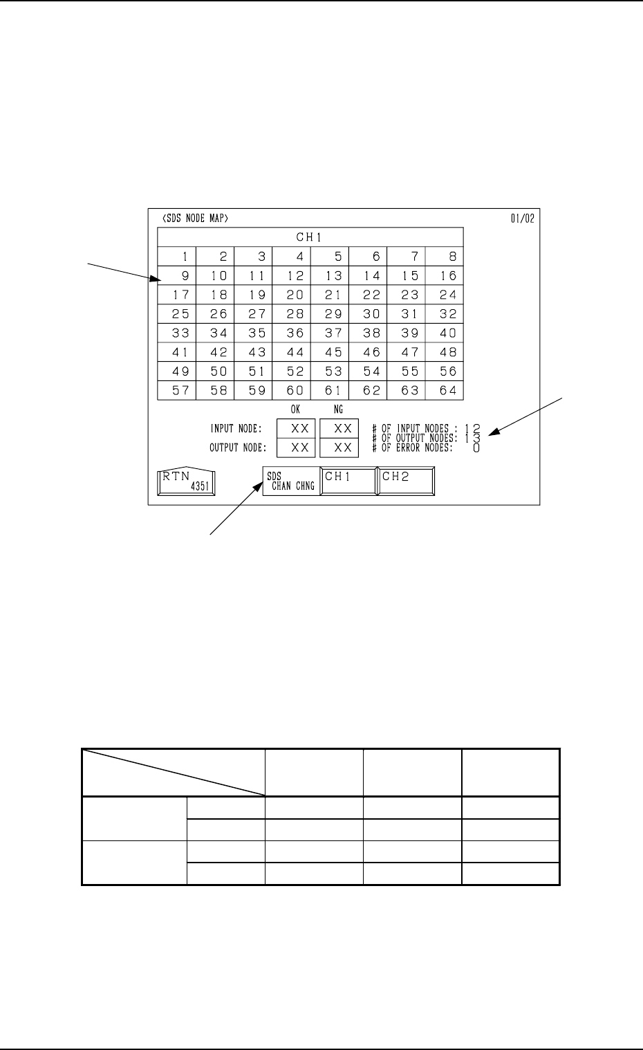
8.1.2 SDS NODE MAP Display
• Shown is the state of the nodes connected to the SDS bus.
When an error is found, check the dip switches of the node P.C.B.
When the [SDS NODE MAP] key is pressed at the “INPUT CHECK” display,
the following display appears on the screen.
*1 “SDS CHAN CHNG” Keys
When the [CH1] key is pressed, Channel 1 is selected. Pressing the [CH2]
key selects Channel 2. The state of the nodes related to the selected channel
is displayed.
*2 State of Nodes
*3 Total of Connected Nodes
Shown are the totals arrived at through the counting of input, output, and
error nodes.
Background
Color
Foreground
Color
Character
Background
Color
Normal Blue White
Input Mode
Error Yellow White Blue
Normal Red White
Output Mode
Error Yellow White Red
Table 3.4
*3
*1
*2
Fig. 3.105