4OM-1064-001.pdf - 第244页
Tg0249-PM-MM 9.4.2 P .E.C. RECOG LIGHTING Display When the [P .E.C. RECOG LIGHTING] key is pressed at the “RECOGNITION LIGHTING” display , the following display appears on the screen. When a lighting unit is selected by …
Tg0249-PM-MM
9. UNIT ADJUSTMENT Display
9910-001 3-197
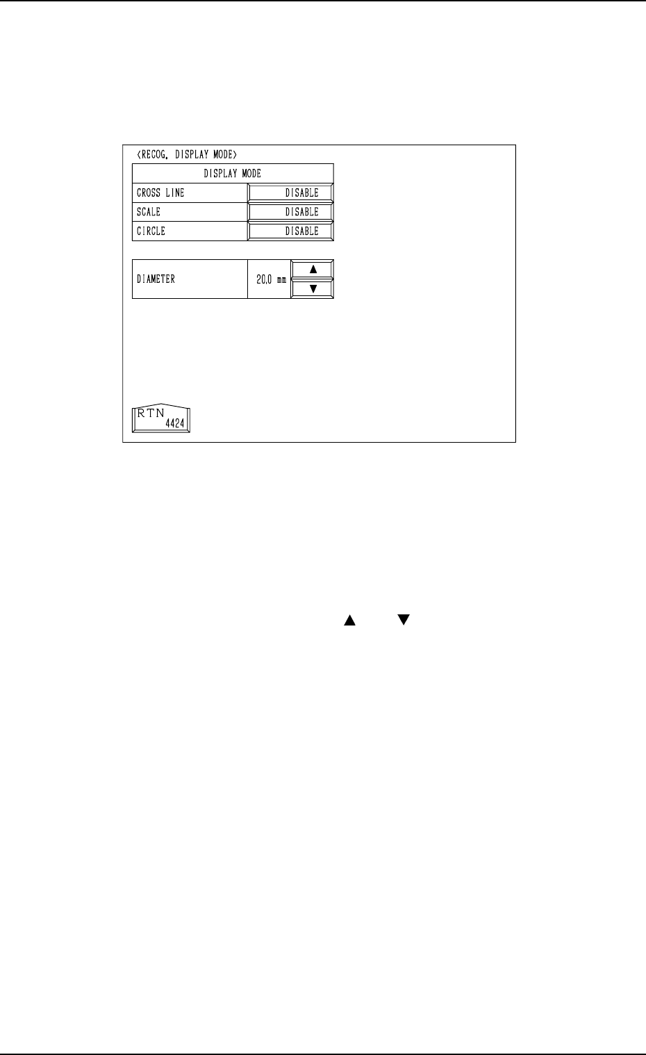
*6 [RECOG. DISPLAY MODE] Key
When this key is pressed, the “RECOG. DISPLAY MODE” display (Fig.
3.116) appears on the screen, enabling the setting of the display mode for
the recognition monitor.
“ENABLE” or “DISABLE” can be set in each data box. For example, when
“ENABLE” is set in the “CROSS LINE” data box, crosslines appear on the
recognition monitor. The same applies to “SCALE” and “CIRCLE”.
When “ENABLE” is set in the “CIRCLE” data box, specify the diameter in
the “DIAMETER” text box.
By pressing the scroll arrow boxes ([
] and [ ]), the diameter of the circle
can be changed.
*7 [MANUAL AXIS OPERATION] Key
When this key is pressed, the “MANUAL AXIS OPERATION” display
appears on the screen, enabling the manual axis operation of each indi-
vidual devices.
The operation is the same as the manual axis operation performed through
manual operations.
Refer to “7. Manual Axis Operation of Section 4 in Volume 1” for details.
Fig. 3.116
Tg0249-PM-MM
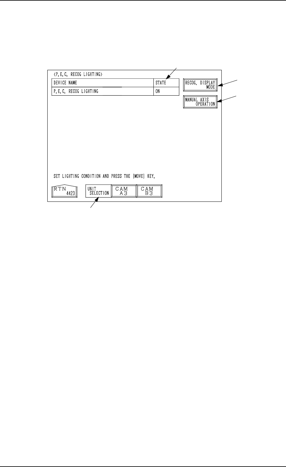
9.4.2 P.E.C. RECOG LIGHTING Display
When the [P.E.C. RECOG LIGHTING] key is pressed at the “RECOGNITION
LIGHTING” display, the following display appears on the screen.
When a lighting unit is selected by pressing the corresponding key beside the
label “UNIT SELECTION” *1 and the [MOVE] button is pressed, the lamps
for P.E.C. recognition lighting can be turned ON or OFF.
*1 UNIT SELECTION
Select a unit for which the lamps for P.E.C. recognition lighting must be
turned ON.
The [CAM A3] or the [CAM B3] key can be selected.
*2 STATE
Shown is the state “ON” or “OFF” of the lamps for P.E.C. recognition light-
ing.
*3 [RECOG. DISPLAY MODE] Key
When this key is pressed, the “RECOG. DISPLAY MODE” display ap-
pears on the screen, enabling the setting of the display mode for the recog-
nition monitor.
Refer to “*6 [RECOG. DISPLAY MODE] Key” in “9.4.1 COMPONENT
RECOG LIGHTING Display” for details.
*4 [MANUAL AXIS OPERATION] Key
When this key is pressed, the “MANUAL AXIS OPERATION” display
appears on the screen, enabling the manual axis operation of each indi-
vidual devices.
The operation is the same as the manual axis operation performed through
manual operations.
Refer to “7. Manual Axis Operation of Section 4 in Volume 1” for details.
9. UNIT ADJUSTMENT Display
9910-001 3-198
Fig. 3.117
*1
*3
*4
*2
9910-001 Tg0249-PM-MM
10. HDD/FDD OPERATION Display
3-199
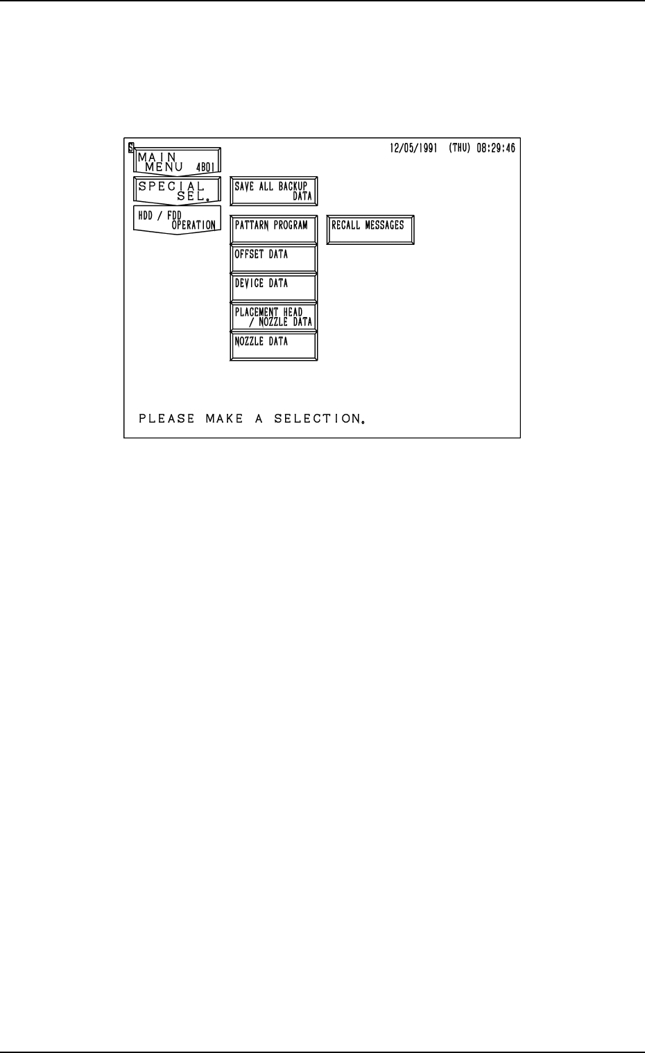
10. HDD/FDD OPERATION Display
When the [HDD/FDD OPERATION] key is pressed at the “SPECIAL SEL.”
display, the following display appears on the screen.
[SAVE ALL BACKUP DATA] Key
All backup data can be saved from the machine side to floppy disks (4
pcs.).
[PATTERN PROGRAM] Key
The pattern program can be saved on or loaded from floppy disks.
[OFFSET DATA] Key
When this key is pressed, the “HDD/FDD OPERATION - OFFSET DATA”
display appears on the screen, enabling you to save the offset data on a
floppy disk or read it from the floppy disk.
[DEVICE DATA] Key
When this key is pressed, the “HDD/FDD OPERATION - DEVICE DATA”
display appears on the screen, enabling you to save the device data on a
floppy disk or read it from the floppy disk.
[PLACEMENT HEAD/NOZZLE DATA] Key
When this key is pressed, the “HDD/FDD OPERATION - PLACEMENT
HEAD /NOZZLE DATA” display appears on the screen, enabling you to
save the nozzle stocker data on a floppy disk or read it from the floppy disk.
[NOZZLE DATA] Key
When this key is pressed, the “HDD/FDD OPERATION - NOZZLE DATA”
display appears on the screen, enabling you to save the nozzle type data on
a floppy disk or read it from the floppy disk.
[RECALL MESSAGES] Key
When this key is pressed, the “HDD/FDD OPERATION - RECALL MES-
SAGES” display appears on the screen, enabling you to save the recalled
data (recalled messages) on a floppy disk or read it from the floppy disk.
Fig. 3.118