4OM-1064-001.pdf - 第44页
Tg0249-PM-MM 2. Replacement Procedure of V acuum Filter (1) Engage the vacuum filter replacement jig with the hook of the cap. (2) Bring the vacuum filter replacement jig straight down and pull out the cap from the place…

Tg0249-PM-MM
Location
Name
Product
No.
Standard and
Material
Part No. Product Name
# of
Attachments
Recommended
# of Year
Remarks
YA-Axis
Driving
Section
S051 #SGDB-20VD-
RY103
630 068 9624 UNIT, DRIVER 1
- x
Driver A (BD)
x YA Axis
YB-Axis
Driving
Section
S051 #SGDB-20VD-
RY103
630 068 9624 UNIT, DRIVER 1
- x
Driver B (BE)
x YB Axis
XA-Axis
Driving
Section
S052 DR2-08ACY103 630 068 9617 UNIT, DRIVER 1
- x
Driver A (BD)
x XA Axis
XB-Axis
Driving
Section
S052 DR2-08ACY103 630 068 9617 UNIT, DRIVER 1
-
x
Driver B (BE)
x XB Axis
Beam-A Head
Up/Down
Driving Shaft
S053 #DR2-01ACY113 630 075 0447 UNIT, DRIVER 2
-
x Driver A (BD)
x LA1 and LA2 Axis
Beam-B Head
Up/Down
Driving Shaft
S053 #DR2-01ACY103 630 075 0447 UNIT, DRIVER 2
- x
Driver B (BE)
x LB1 and LB2 Axis
DD Motor
Driving
Section
S251 #D2332 630 053 1664 UNIT, DRIVER 4
- x
X/Y Wiring (CB)
x ZA1 and ZA2 Axis
ZB1 and ZB2 Axis
Backup
Driving
Section
S158 #DR2-02AC-433 630 062 9071 UNIT, DRIVER 1
-
x
Driver A (BD)
x BPC Axis
Conveyor
Width Driving
Section
S061 #AK-BX501V-
SAT4
630 051 6555 UNIT, DRIVER 1
- x
Conveyor 2 (BL)
x PWC Axis
Tray Traverse
Shaft
S051 #AK-BX501-
SAT2
630 059 3853 UNIT, DRIVER 2
- x
Tray Traverse (TT)
x TT1 and TT2 Axis
Feeder Shaft S955 AK-BX551PV-
SAT10
630 071 9529 UNIT, DRIVER 4
- x
Main Body (BB)
x TF (A1) Axis, TF
(A2) Axis, TF (B1)
Axis, and TF (B2)
Axis
1. List of Consumables and Important Servicing Parts
Mechanical Parts Table 2.3
Location
Name
Product
No.
Standard and
Material
Part No. Product Name
# of
Attachments
Recommended
# of Year
Remarks
Tape Feed
Speed Cam
S119 CFN10R-A 630 034 0020 CAM
FOLLOWER
82
x Feeder Base N
Vacuum
Pump
S005 #3-040437-1 630 055 2915 VACUUM PUMP 1 2
x Vacuum Pump
Electrical Parts Table 2.4
0103-003 2-3
1.2 List of Important Servicing Parts
Listed below are the parts that may be consumed in several years.
The list below is provided for your reference.
Note : Since replacement work of important servicing parts requires highly
sophisticated technique, consult our servicing personnel for details.
Tg0249-PM-MM
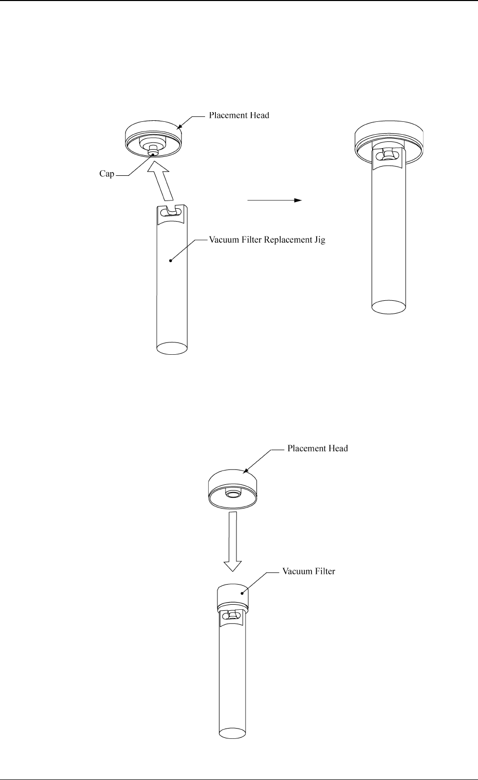
2. Replacement Procedure of Vacuum Filter
(1) Engage the vacuum filter replacement jig with the hook of the cap.
(2) Bring the vacuum filter replacement jig straight down and pull out the
cap from the placement head.
Note: The vacuum filter replacement jig should not come off from the
cap.
Fig. 2.1-2
2. Replacement Procedure of Vacuum Filter
9910-001 2-4
Fig. 2.1-1
Fig. 2.2
Tg0249-PM-MM
9910-001 2-5
2. Replacement Procedure of Vacuum Filter
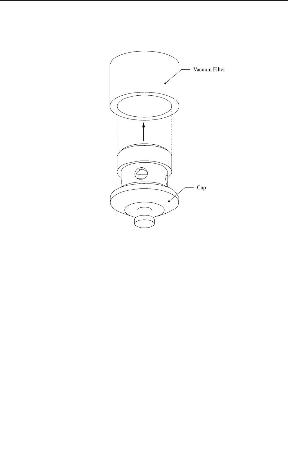
Fig. 2.3
(3) Detach the vacuum filter from the cap.
Note: Do not throw away the cap.
(4) Attach a new vacuum filter to the cap.
(5) Engage the vacuum filter replacement jig with the hook of the cap and
push the cap straight into the placement head in the reverse order of cap
detachment.
Note: Push the cap into the placement head as far as possible.
(6) Follow the reverse procedure of the jig engagement (engagement proce-
dure for vacuum filter replacement jig) to slide it out horizontally from
the hook of the cap.