4OM-1064-001.pdf - 第89页
9910-001 Tg0249-PM-MM 5. 2 MANUAL COMPONENT RECOGNITION CAMERA BYP ASS Display When the [MNL. COMP . RECOG CAMERA BYP ASS] key is pressed at the “MANUAL BYP ASS” display , the following display appears on the screen. Col…
9910-001 Tg0249-PM-MM
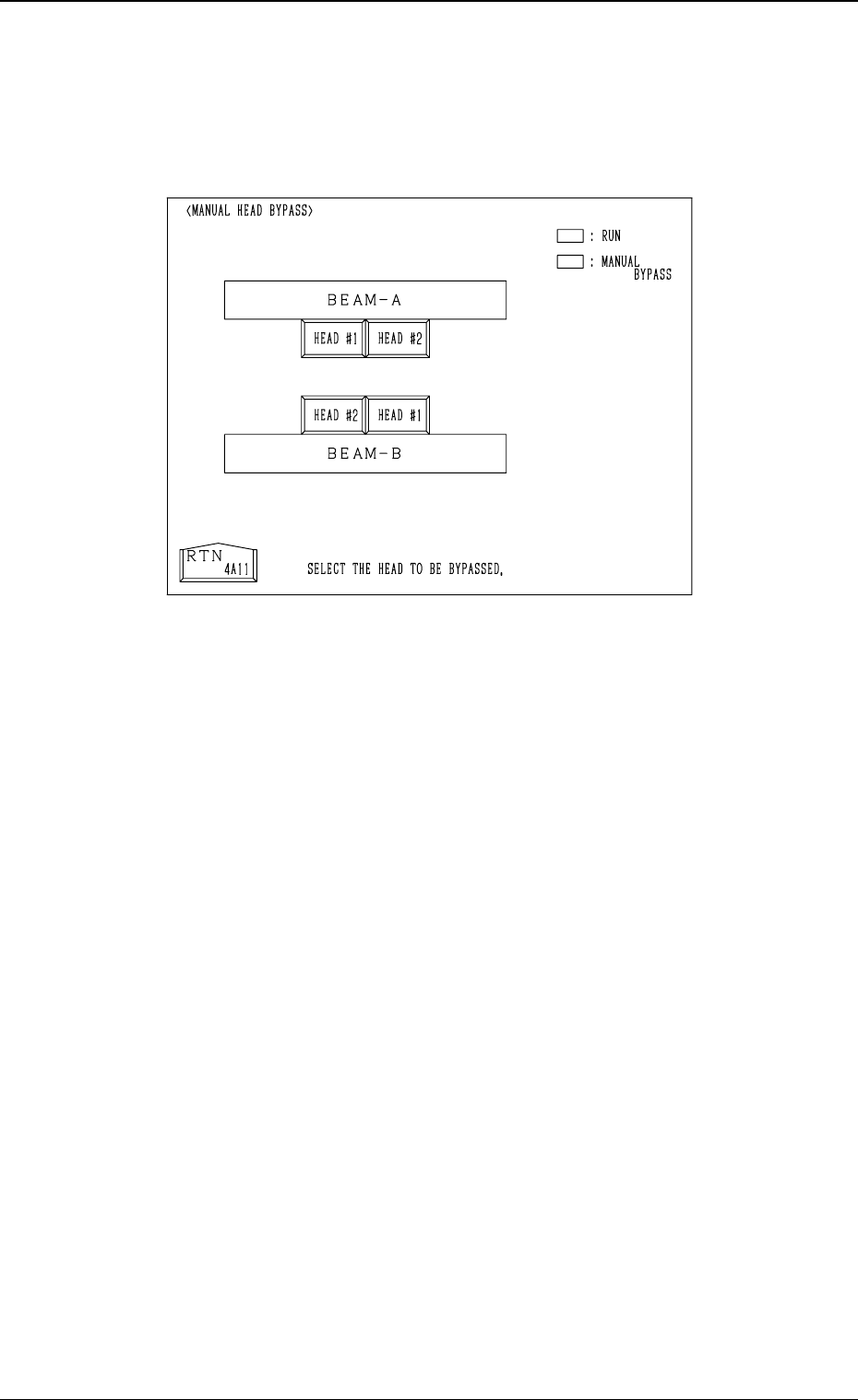
5.1 MANUAL HEAD BYPASS Display
When the [MANUAL HEAD BYPASS] key is pressed at the “MANUAL BY-
PASS” display, the following display appears on the screen.
Color of Head # Keys
• Case: A head is not bypassed.
Line and Foreground Color: Green
Background Color: Black
• Case: A head is bypassed.
Line and Foreground Color: Yellow
Background Color: Blue
Operation Procedure
• Select the head # key to be bypassed.
The selected key turns blue.
• To cancel the bypass setting, select the head # key again.
3-42
5. MANUAL BYPASS Display
Fig. 3.28-1
9910-001 Tg0249-PM-MM
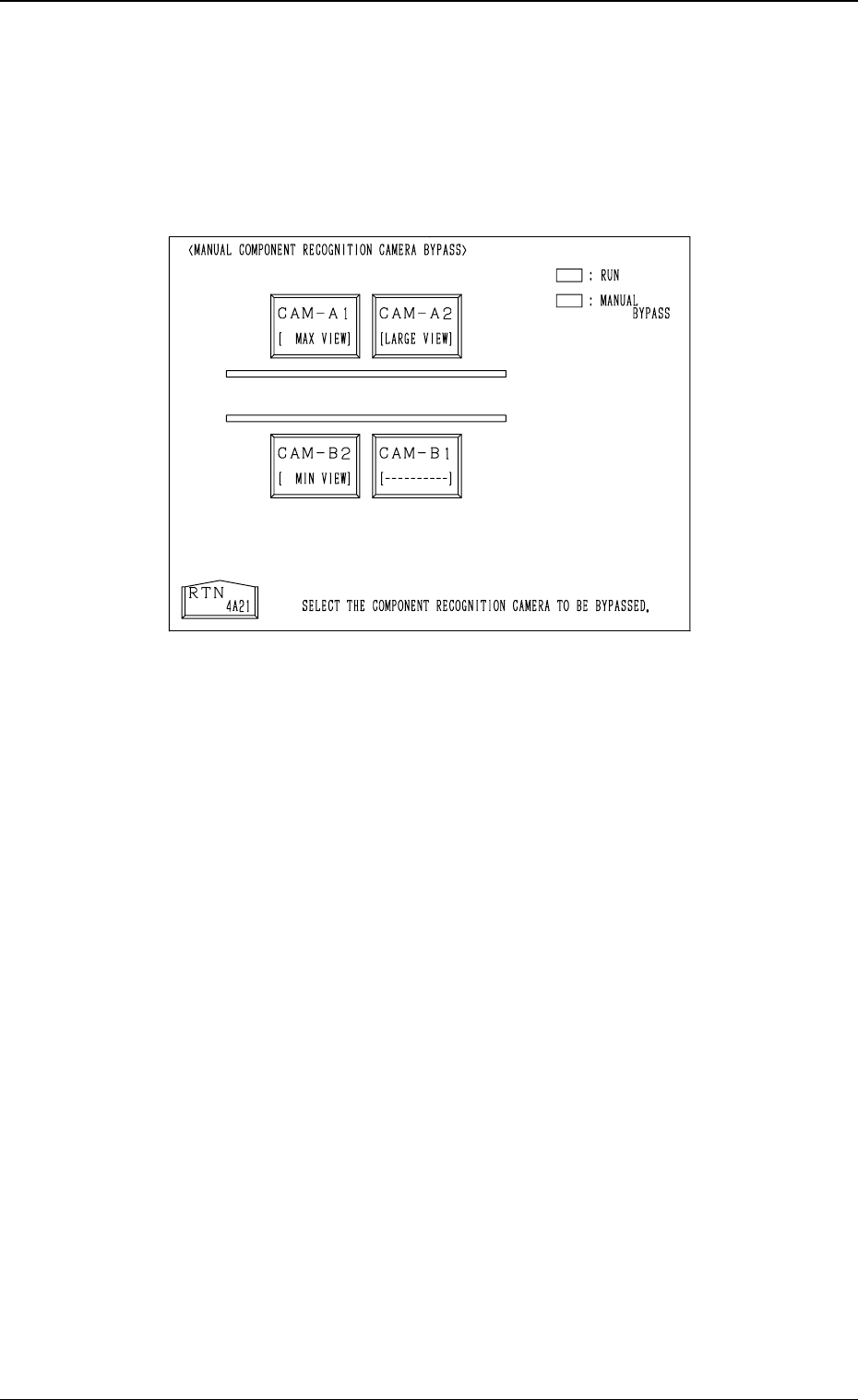
5.2 MANUAL COMPONENT RECOGNITION CAMERA
BYPASS Display
When the [MNL. COMP. RECOG CAMERA BYPASS] key is pressed at the
“MANUAL BYPASS” display, the following display appears on the screen.
Color of Camera # Keys
• Case: A camera is not bypassed.
Line and Foreground Color: Green
Background Color: Black
• Case: A camera is bypassed.
Line and Foreground Color: Yellow
Background Color: Blue
Operation Procedure
• Select the camera # key to be bypassed.
The selected key turns blue.
• To cancel the bypass setting, select the head # key again.
3-43
5. MANUAL BYPASS Display
Fig. 3.28-2
Tg0249-PM-MM
6. TEACH OFFSET Display
CAUTION
• The accuracy of component placement is af-
fected by the teaching operations. Only our
service personnel or a trained one shall per-
form teaching operations.
• Some operations require special jigs (option).
Consult our sales personnel before perform-
ing any teaching operations.
• Follow the teaching procedures in the speci-
fied order. Otherwide, some trouble (such as
inaccurate component placement, frequent
mechanical errors, etc.) will arise.
• Before performing the teaching operation,
check that the component recognition offset
jig, the jig location, and the back light stage
(teaching plate) are not nicked nor stained.
Refer to
“6. Monthly Maintenance of Section
1
” for details.
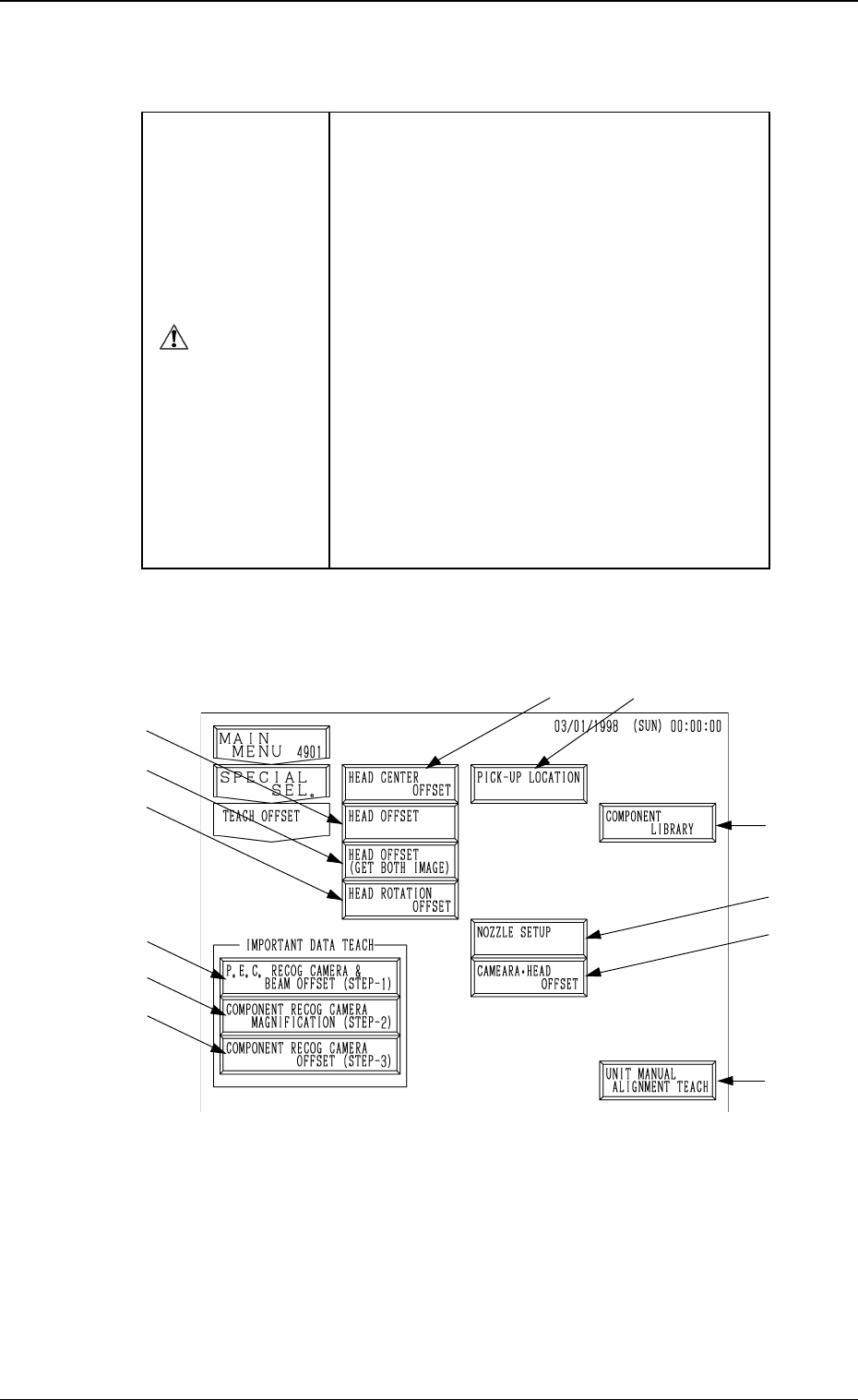
When the [TEACH OFFSET] key is pressed at the “SPECIAL SEL.” display,
the following display appears on the screen.
Note: The -marked function is optional.
*1 [P.E.C. RECOG CAMERA & BEAM OFFSET (STEP-1)] Key
When this key is pressed, the “P.E.C. RECOG CAMERA & BEAM OFF-
SET (STEP-1)” display appears on the screen, enabling to teach the X/Y
beam and P.E.C. camera offset data.
Note: A special jig P.C.B. (option) is required.
The parameters are factory-set at shipment. It is not necessary to
teach these parameters.
*1
*2
*3
*4
*10
*11
*8
*9
0004-002 3-44
6. TEACH OFFSET Display
Fig. 3.29
*5
*6
*7