4OM-1064-001.pdf - 第9页
Contents Page Section 5 T ouch Screen ................................................................... 5- 1 1. SCREEN ADJUSTMENT Display ................................................... 5- 2 2. RGB (Red-Green-Blue …

Contents
Page
7.2.5 COMPONENT RECOG. TEST - TRAY COMPONENT
SUPPLY/STORAGE Display (Option) .............................. 3-149
7.2.6 Result of Component Recognition .................................... 3-150
7.2.7 Procedure for Component Recognition Test ..................... 3-151
7.3 X/Y BEAM TEST Display ......................................................... 3-156
8. DEVICE CHECK Display ............................................................... 3-159
8.1 INPUT CHECK Display ........................................................... 3-160
8.1.1 DIO, SDS CH1, SDS CH2, Interlock, Motor Control ......... 3-161
8.1.2 SDS NODE MAP Display .................................................. 3-179
8.1.3 SDS STATUS Display ....................................................... 3-180
8.1.4 Setting of SDS Nodes ....................................................... 3-181
8.1.5 FEEDER UNIT SET-UP INFORMATION Display ............. 3-186
8.2 MACHINE PROGRAM INFORMATION Display ..................... 3-187
9. UNIT ADJUSTMENT Display ........................................................ 3-188
9.1 CONVEYOR TIMER ADJUSTMENT Display .......................... 3-189
9.2 FEEDER BASE Display .......................................................... 3-191
9.3 CONVEYOR ADJUSTMENT Display ...................................... 3-193
9.4 RECOGNITION LIGHTING Display ........................................ 3-195
9.4.1 COMPONENT RECOG LIGHTING Display ..................... 3-196
9.4.2 P.E.C. RECOG LIGHTING Display ................................... 3-198
10. HDD/FDD OPERATION Display ................................................. 3-199
10.1 SAVE ALL BACKUP DATA Display ....................................... 3-200
10.2 SAVE/LOAD PATTERN PROGRAM Display......................... 3-202
10.3 HDD/FDD OPERATION - OFFSET DATA Display ................ 3-204
10.4 HDD/FDD OPERATION - DEVICE DATA Display ................. 3-206
10.5 HDD/FDD OPERATION - NOZZLE STOCKER
DATA Display......................................................................... 3-207
10.6 HDD/FDD OPERATION - NOZZLE TYPE DATA
INFO. Display ........................................................................ 3-208
10.7 HDD/FDD OPERATION - RECALL MESSAGES Display ..... 3-210
Section 4 Machine Set-Up Menus ................................................. 4- 1
1. Hierarchical Structure of Machine Set-Up Displays ........................ 4- 2
2. MACHINE SET-UP Display ............................................................. 4- 3
3. Management of Password .............................................................. 4- 4
3.1 Setting of Password Available Areas ........................................ 4- 5
3.2 Flow of Operation ...................................................................... 4- 6
3.3 Setting of Passwords ................................................................ 4- 9
4. Setting of Light Tower and Alarm Data ........................................... 4-11
5. Setting of Date and Time Data ........................................................ 4-13
6. Setting of Error Display Colors ........................................................ 4-14
7. Screen Mode Function .................................................................... 4-15
8. CUSTOMIZE Display....................................................................... 4-17
9910-001 6 Tg0249-PM-MM

Contents
Page
Section 5 Touch Screen ................................................................... 5- 1
1. SCREEN ADJUSTMENT Display ................................................... 5- 2
2. RGB (Red-Green-Blue Signal) Adjustment ..................................... 5- 5
3. DATA SAVE MODE Display ............................................................ 5- 6
9910-001 7 Tg0249-PM-MM
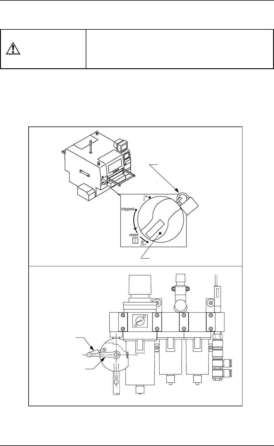
WARNING
Precautionary Measures in Maintenance and Inspection Work
0004-002 8 Tg0249-PM-MM
Before performing maintenance work, turn off the
power switch and the air source of the machine
and lock the power breaker using the padlock.
• Designate a personnel who can have charge of the
padlock key.
•
If the provided padlock is lost or damaged, purchase its
substitute.
Power Breaker
Padlock
(No. 2500 30 MM)
Precautionary Measures in Maintenance and
Inspection Work
Padlock
Main Valve