4OM-1064-001.pdf - 第92页
Tg0249-PM-MM Notes: (a) When “P .E.C. Recognition Camera & Beam Offset (Step 1)” must be taken, perform the teaching operation of [T eaching Plate Off- set] before [Component Recognition Camera Offset (Step 3)]. In t…

Tg0249-PM-MM
9910-001 3-45
6. TEACH OFFSET Display
*2 [COMPONENT RECOG CAMERA MAGNIFICATION (STEP-2)] Key
When this key is pressed, the "COMP. RECOG. CAMERA MAG. (STEP-
2)" display appears on the screen, enabling to teach the magnification of
the component recognition camera.
Note: A special jig (option) is required. The parameters are factory-set at
shipment. It is not necessary to teach these parameters.
*3 [COMPONENT RECOG CAMERA OFFSET (STEP-3)] Key
When this key is pressed, the "COMP. RCG. CAMR. OFST. (STEP3)"
display appears on the screen, enabling to teach the component recognition
camera offset data.
*4 [HEAD CENTER OFFSET] Key
When this key is pressed, the "HEAD CENTER OFFSET" display appears
on the screen, enabling to teach the head center offset data.
*5 [HEAD OFFSET] Key
When this key is pressed, the "HEAD OFFSET" display appears on the
screen, enabling to teach the head offset data.
*6 [HEAD OFFSET (GET BOTH IMAGE)] Key
When this key is pressed, the "HEAD OFFSET (GET BOTH IMAGE)"
display appears on the screen, enabling the teaching operation of the head
position offset for the simultaneous image capture function.
*7 [HEAD ROTATION OFFSET] Key
When this key is pressed, the "HEAD ROTATION OFFSET" display ap-
pears on the screen, enabling to teach the head rotation offset data.
Note: A special jig NOZZLE (option) is required. The parameters are
factory-set at shipment. It is not necessary to teach these param-
eters.
*8 [UNIT MANUAL ALIGNMENT TEACH] Key
When this key is pressed, the "UNIT MANUAL ALIGNMENT TEACH"
display appears on the screen, enabling to teach the offset data for the units
such as the feeder, the nozzle stocker, etc.
*9 [PICK-UP LOCATION] Key
When this key is pressed, the "PICK-UP LOCATION" display appears on
the screen, enabling to teach the component pick-up location through manual
alignment operation.
*10 [NOZZLE SETUP] Key
When this key is pressed, the “NOZZLE SETUP” display appears
on the screen, enabling to setup the nozzle.
*11 [CAMERA-HEAD OFFSET] Key
When this key is pressed, the “CAMERA HEAD OFFSET” display
appears on the screen, enabling to teach camera-head offset.
Tg0249-PM-MM
Notes: (a) When “P.E.C. Recognition Camera & Beam Offset (Step 1)” must
be taken, perform the teaching operation of [Teaching Plate Off-
set] before [Component Recognition Camera Offset (Step 3)].
In this case, also perform the following teaching operation after
teaching of “Head Offset (Get Both Image)” is complete.
“Nozzle Stoker Offset”
“Traverse Offset (Option)”
(b) After the head section is changed, perform the teaching operation
on the lighting at the “LIGHTING” display before “Component
Recognition Camera Magnification (Step 2)”. (Hierarchical Se-
quence: “SPECIAL SEL.” Display → “UNIT ADJUSTMENT”
Display → “LIGHTING” Display)
0004-002 3-46
6. TEACH OFFSET Display
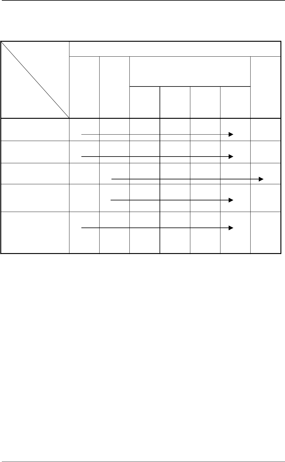
Order of Teaching Operations: The {-marked items should be implemented
sequentially from the left to the right one.
Camera head offset teaching available
Teaching Items
Operational Items
P. E . C .
Recognition
Camera &
Beam Offset
(Step 1)
Component
Recognition
Camera
Magnification
(Step 2)
Component
Recognition
Camera
Offset
(Step 3)
Head
Center
Offset
Head
Offset
Head
Offset
(Get Both
Image)
Head
Rotation
Offset
P.C.B. Recognition
Camera Change
{
*1
{
*2
{
*3
{
*4
{
*5
Motor for Readjustment of
Beam Origin, Slide Origin
Sensor Change, Others
{
*1
{
*2
{
*3
{
*4
{
*5
Change of Head Section
Note: (b)
{
*1
{
*2
{
*3
{
*4
{
*5
{
*6
Component Recognition
Camera Change
(View Change, etc.)
{
*1
{
*2
{
*3
{
*4
{
*5
Maintenance of P.C.B.
Positioning Section
x Stopper Change
xTransfer Section including
Fixed Chute
Unit Change
{
*1
{
*2
{
*3
{
*4
{
*5
Table 3.3 List of Operational and Teaching Items
(items which require the offset teaching)
Tg0249-PM-MM
*5
*6
*8
*10
*7*9
*11
*4
*3
*3
*2
*1
9910-001 3-47
6. TEACH OFFSET Display
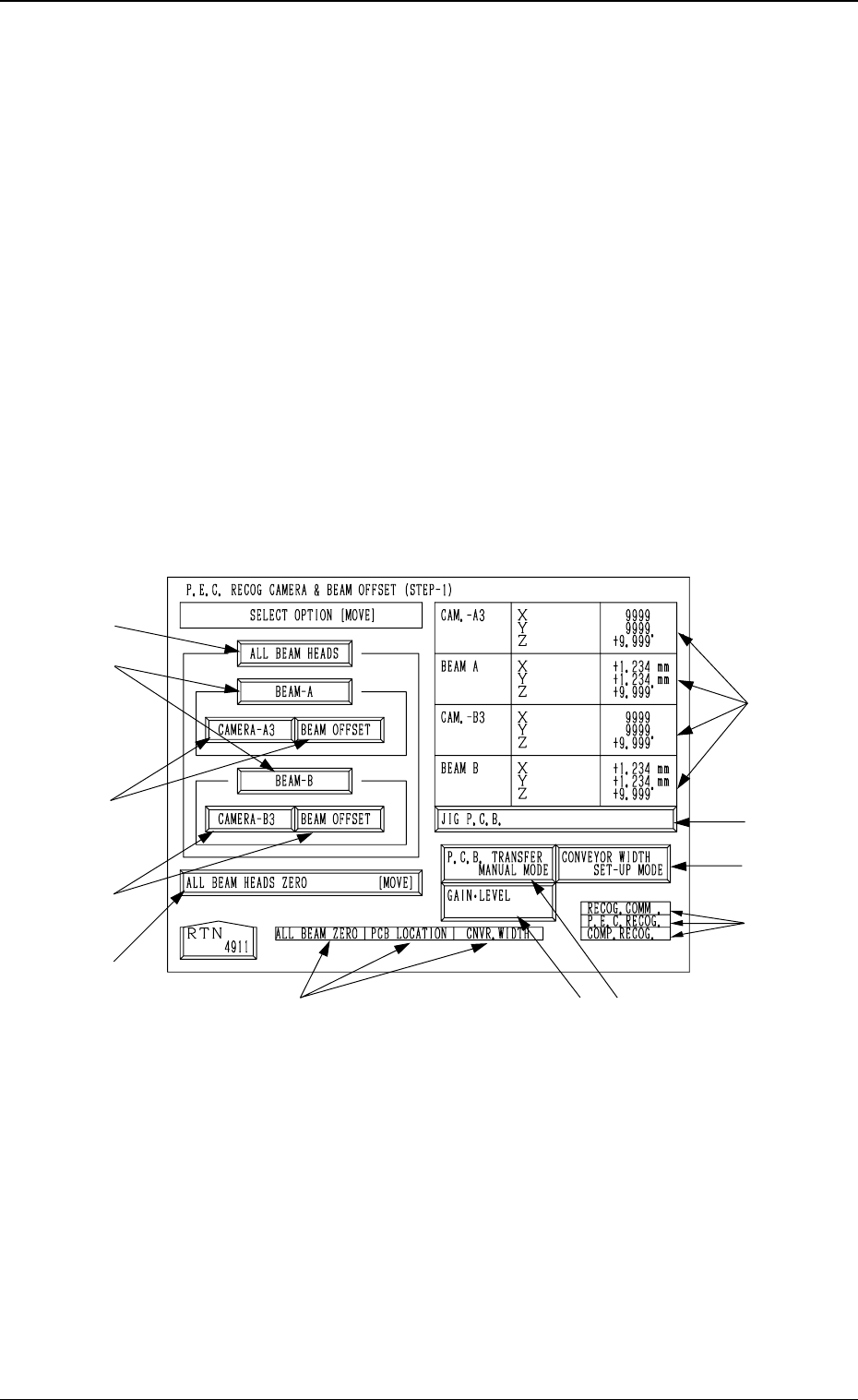
Fig. 3.30
6.1 P.E.C. RECOG CAMERA & BEAM OFFSET
(STEP-1) Display
• This display allows teaching the offset data for Beams A and B and the
offset data for the P.E.C. recognition camera.
The patterns printed on the positioned special jig P.C.B. (option) are recog-
nized by the P.E.C. recognition camera and each offset data is calculated
through the recognition.
Notes: (a) A special jig P.C.B. (option) is required.
The parameters are factory-set at shipment. It is not necessary to
teach these parameters.
(b) Follow the teaching procedures in the specified order. Otherwise,
some trouble (such as inaccurate component placement, frequent
mechanical errors, etc.) will arise.
When the [P.E.C. RECOG CAMERA & BEAM OFFSET (STEP-1)] key is
pressed at the “TEACH OFFSET” display, the following display appears on
the screen.