Horizon UserManualV6.pdf - 第148页
When a particular print stroke is being monitored, as the squeegee traverses the image the pressure being applied is measured and recorded. Any variations in the load being applied, as a result of insufficient tooling su…

Paste Trails Provides the capability to reduce solder paste trails from squeegees
automatically, options are:
Disabled; Mode 1
If mode 1 is selected, any paste that has dripped from the squeegee is scooped up,
by the squeegee back to the paste roll. This process occurs at the start of every
stroke, with the print mode set to print/print and at the start of only the print
stroke, when the print mode is set to flood/print or print/flood.
Transport Wait
Mode
This option enables the product to be held in contact with the screen until both
upline and downline systems are ready to transfer, options are:
Standard; Hold_at_Print
The default is Standard.
Clamp Type Sets the type of board clamp used, options are:
Board Clamp; Snuggers
The default is Board Clamps.
To eliminate vacuum seal loss during alignment, if the Snuggers option is
selected and the tooling type is Vacuum, the rails do not dip when the camera is
traversing.
Snugger Thickness This parameter is only available if Snuggers has been selected from the Clamp
Type preference, options are:
Min 0.8mm
Max 2.0mm (2.01mm is displayed but 2.0mm is the maximum value selectable)
Increments 0.1mm
The default is 1.6mm.
Tooling Monitoring This parameter sets, while Feature Licensing asserts that use of Tooling
Deviation Monitoring is authorized, the frequency (in boards printed) at which
monitoring is performed. Monitoring is also carried out on the first print stroke
of a print run.
Min 0 boards (Tooling Monitoring disabled)
Max 200 boards
Increments 1
The default is 0 boards.
This feature only applies while squeegees are fitted.
Software Version 6 User Manual 2.13
SET PREFERENCES
PREFERENCES
When a particular print stroke is being monitored, as the squeegee traverses the
image the pressure being applied is measured and recorded. Any variations in
the load being applied, as a result of insufficient tooling support or underside
components coming into contact with the tooling are noted. Upon completion of
the print stroke, the deviation in the pressure applied over the print stroke is
determined and expressed as the tooling deviation. The tooling deviation is
calculated from the minimum and maximum values and expressed as a
percentage. If the tooling deviation exceeds the permitted threshold, as set by
the Tooling Deviation parameter in the product file, a cyclic log text file called
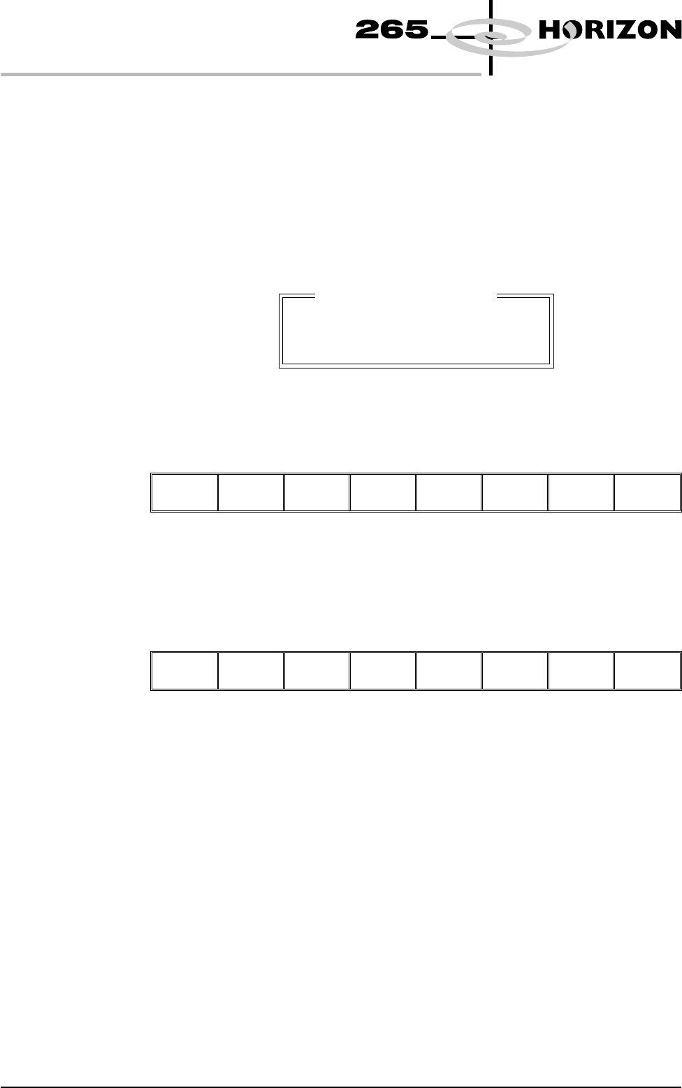
deviate.dat is written and the following window is displayed:
NOTE
The number of samples is the amount of pressure variations recorded during the
print stroke.
The following menu bar is displayed:
Continue Abort
On selecting Continue printing proceeds until it is interrupted by some other
cause.
On selecting Abort printing is discontinued and the following menu bar is
displayed, to enable the board to be removed from the machine:
Auto
Board
Manual
Board
Exit
If the number of samples (pressure variations) during a print stroke is less than 2
or the minimum value is zero, the error message ‘Failed to determine Tooling
Deviation’ is displayed.
Display Type Sets the type of status page displayed on the monitor, options are:
Type 1; Type 2
The default is Type 1.
2.14 User Manual Software Version 6
SET PREFERENCES
PREFERENCES
Excessive Tooling Deviation
Tooling Deviation : 25.08 %
Number of Samples : 81
Check the Board Support.
Fiducial
Monitoring
This parameter enables and disables the intelligent fiducial monitoring feature,
options are:
Smart; Normal
The default is Normal.
If smart is selected, a set levels menu bar option is available.
Set
Levels
Next Previous Incr. Decr. Exit
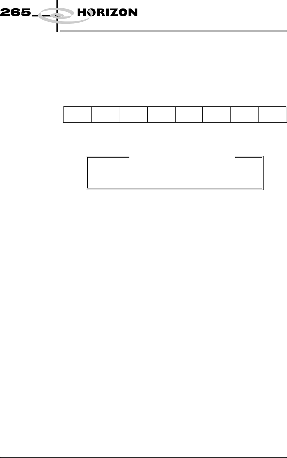
On pressing the Set Levels key, a window opens as follows:
The Next and Previous keys move the cursor between the three parameters.
The Incr. and Decr. keys increase and decrease the value of the top two
parameters and turn the Automatic Retry On and Off.
The Exit key closes the window and returns to the set preferences window.
The range of values for the three parameters are as follows:
Score Warning Level:
Min 0
Max 500
Var’n Warning Level:
Min 0
Max 500
Automatic Retry:
Off; On
Score Warning
Level
During fiducial set up the score achieved after training each fiducial is analyzed.
If the score fails to achieve the accept score by more than Score Warning Level,
an instruction box appears recommending the operator check video settings,
fiducial parameters etc.
Var’n Warning
Level
While the machine is running, the score for every fiducial located is monitored.
If for a given fiducial, the score from one fiducial to the next varies by more than
the Variation Warning Level, but does not fall below the minimum accept score,
a message window is displayed, warning that the score of the screen/board
fiducial is fluctuating. Fiducial relearning is advised if the problem persists.
Software Version 6 User Manual 2.15
SET PREFERENCES
PREFERENCES
SMART FIDUCIAL MONITORING
SCORE WARNING LEVEL
VAR'N WARNING LEVEL
AUTOMATIC RETRY
500
10
OFF