Horizon UserManualV6.pdf - 第18页
STAGE 1 For machines with the remote board stop option, ensure that the machine is correctly configured for the intended product. Carry out the appropriate one of the following procedures: • Camera to Remote Board Stop -…
MACHINE PROGRAMMING
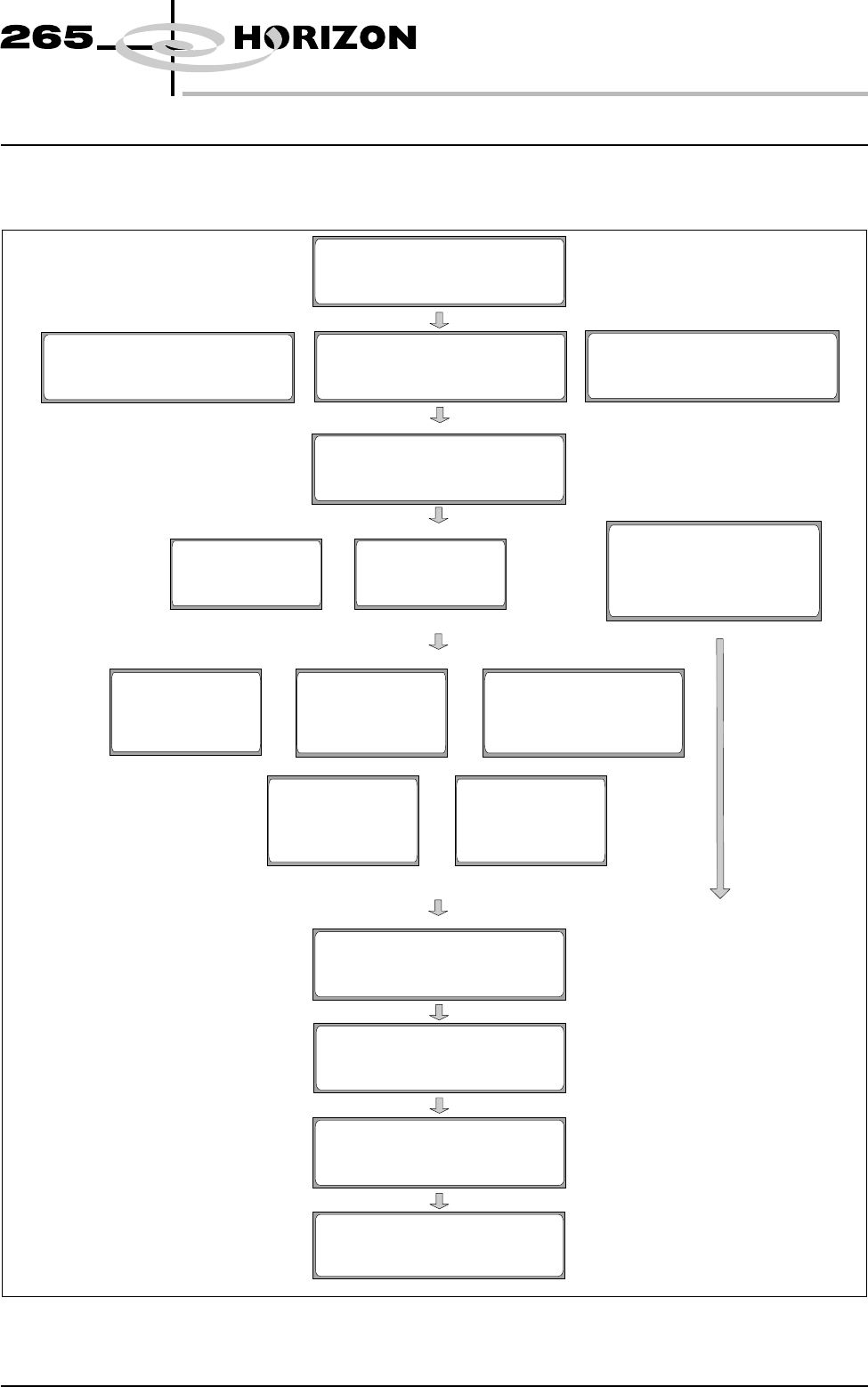
INTRODUCTION This chapter details the procedure for a product setup, in stages and are as
follows:
Software Version 6 User Manual 1.1
MACHINE PROGRAMMING
INTRODUCTION
STAGE 1
PowerUpandLogOn
STAGE 2B
Loading a Product File -
Using Bar Code
STAGE 2A
Loading a Product File -
Using Function Keys
STAGE 2C
Loading a Product File -
Using Pocket Off Line Editor
STAGE 3
Editing a Product File
STAGE 7
Load Paste
Run a Product in Step Mode
STAGE 8
2Di Setup
STAGE 9
Running a Product
in Run Mode
STAGE 6
Vision System Setup
STAGE 5B
Tooling Setup -
Vacuum
& Load Screen
STAGE 5A
Tooling Setup -
Magnetic Pillars
& Load Screen
STAGE 5C
Tooling Setup -
Dedicated Tooling System
& Load Screen
STAGE 5D
Tooling Setup -
MultiFlex
& Load Screen
STAGE 5E
Tooling Setup -
AutoFlex
& Load Screen
STAGE 4A
Fit Squeegees
STAGE 4B
ProFlow Setup
STAGE 4C
Tooling Setup - FormFlex
Load Screen &
Fit Squeegees/ProFlow
STAGE 1 For machines with the remote board stop option, ensure that the machine is
correctly configured for the intended product. Carry out the appropriate one of
the following procedures:
•
Camera to Remote Board Stop - LHS Configuration
•
Camera to Remote Board Stop - RHS Configuration
•
Remote Board Stop - LHS to RHS Configuration
•
Remote Board Stop - RHS to LHS Configuration
•
Remote Board Stop - Same Side Configuration
•
Remote Board Stop to Camera Board Stop
See Technical Reference Manual, Rising Table Module Chapter, Replacement
Procedures, for the first five procedures and Technical Reference Manual,
Camera and Vision System Module Chapter, Replacement Procedures for the
Remote Board Stop to Camera Board Stop procedure.
Power Up and
Log On
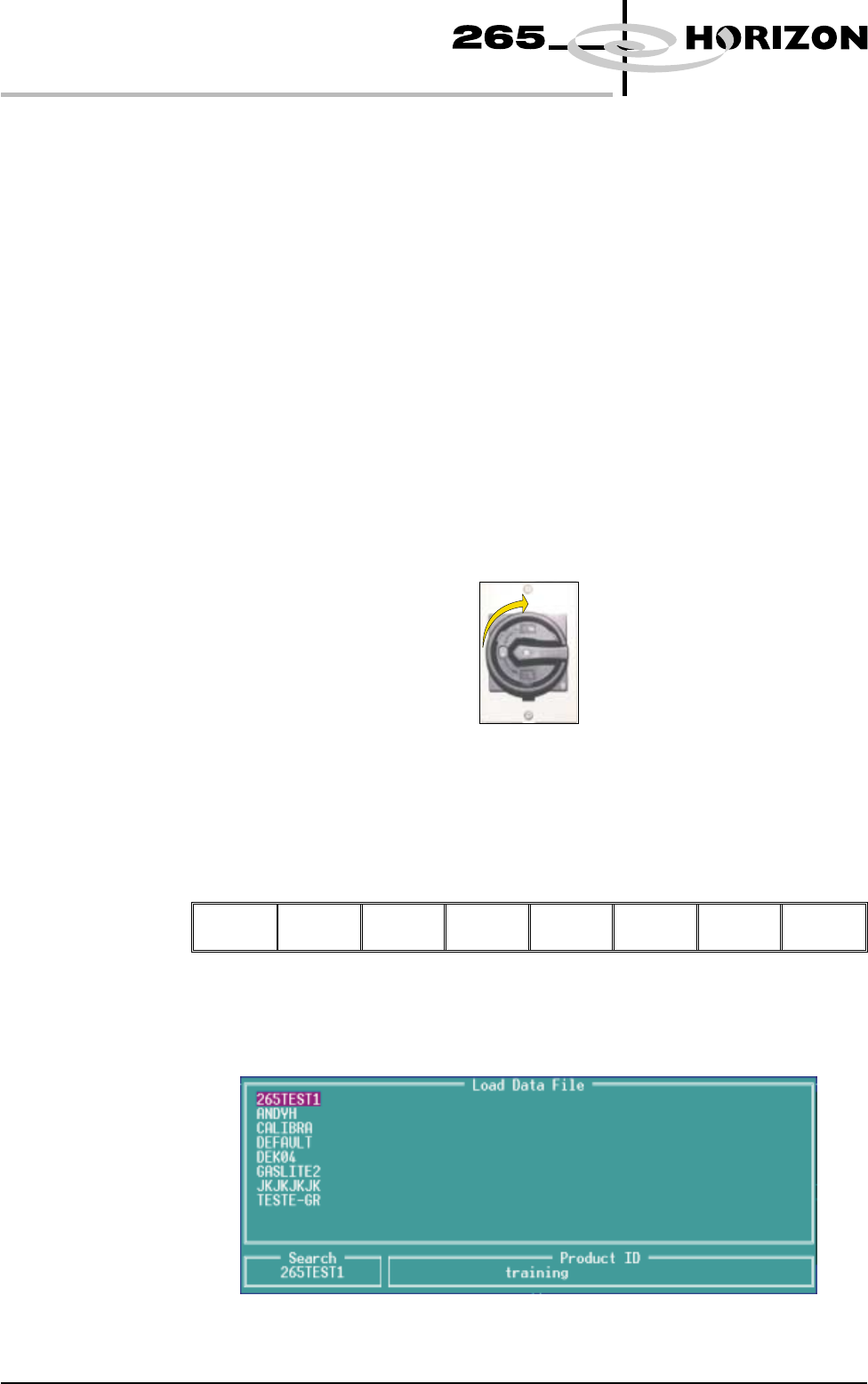
1. Turn the mains isolator switch to On.
2. When the message ‘Press SYSTEM Switch To Initialize Printer or Select
Diagnostics or Load Data’ is displayed in the message prompt bar, either:
a) Select Load Data (F2) if the loaded product is unknown or needs to be
changed.
b) Go to Step 5 if the loaded product file is known to be the correct one.
Load
Data
Diagnost
The following Load Data File window is displayed:
1.2 User Manual Software Version 6
MACHINE PROGRAMMING
STAGE 1
3. Use Left, Right, Up or Down function keys (F4-F7) to highlight the
required file.
Load Rebuild
List
Left Right Up Down
Exit
4. Press Load (F1).
Load
Rebuild
List
Left Right Up Down Exit
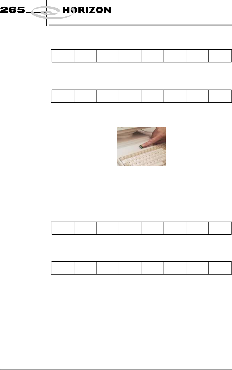
5. Initialize the machine by pressing the System button.
The selected file is now displayed on the status page.
The operator can change the language used in the display menus.
To select a different language continue with Step 6. If the correct language is
loaded go to Step 12.
6. Select Setup (F6).
Run Open
Cover
Paste
Load
Clean
Screen
Adjust
Setup
Monitor Maint.
7. Select Change Language (F7).
Mode Load
Data
Edit
Data
Setup
Squeegee
Change
Screen
Change
Tooling
Change
Language
Exit
8. A list of installed languages is displayed. Select Up (F5), or Down (F6) until
the desired language is highlighted.
Software Version 6 User Manual 1.3
MACHINE PROGRAMMING
STAGE 1