Horizon UserManualV6.pdf - 第261页
For the green camera the lighting parameters and their functions are shown below. Inspection Setup Correct inspection setup is the key to effective inspection. By following the steps of the setup sequence, shown in the s…
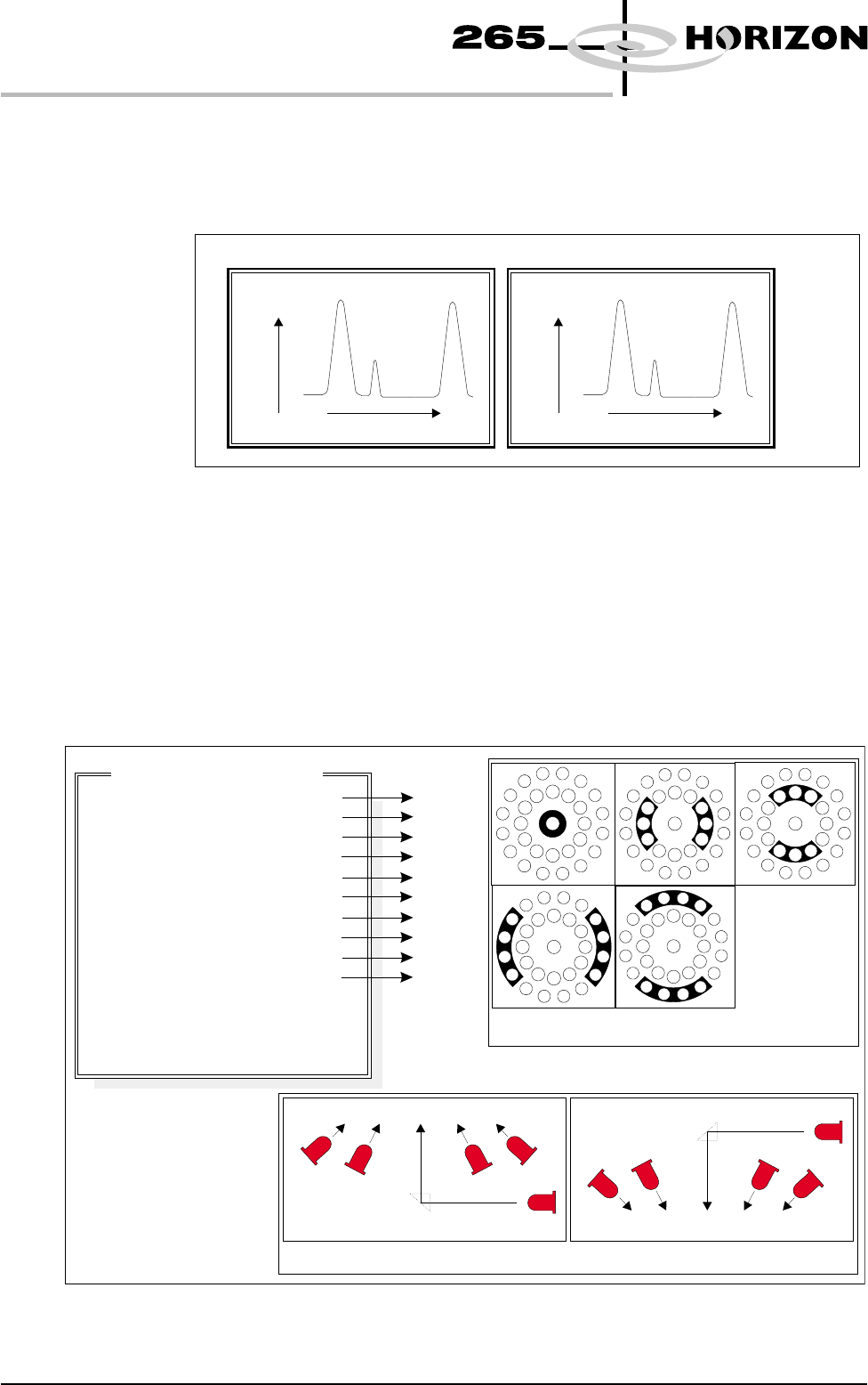
Histogram The Cognex card analyses the grey scale levels, of the pixels that make up the
site image. From this information a histogram is produced, which can be used as
a visual aid to setting up 2Di inspection.
Lighting The lighting levels for 2Di inspection are software controlled. For a more
detailed description of the camera and optical unit refer to the Technical
Reference Manual, Camera and Vision Systems Module Chapter.
The GSX and Lt machines use either the silver or green cameras. The Horizon
and Infinity machines use only the green camera.
For the silver camera the lighting parameters and their functions are shown
below.
8.10 User Manual Software Version 6
2Di INSPECTION
MODULE OVERVIEW
Screen Histogram Board Histogram
No.ofPixels
Black
Screen
Aperture
Pa s t e
White
No.OfPixels
Black
Pa d
Board
Pa s t e
White
Grey Scale Level
Grey Scale Level
Figure 8-9 Screen and Board Histograms
8
8
8
8
8
8
8
8
8
8
-1.0
-1.5
2.0
2.0
Inspection Lighting Parameters
Screen Vertical
Screen Inner LR
Screen Inner FR
Screen Outer LR
Screen Outer FR
Board Vertical
Board Inner LR
Board Inner FR
Board Outer LR
Board Outer FR
Window Left
Window Top
Window Width
Window Height
A
B
C
D
E
A
B
C
D
E
NOTE
LR = Left and Right
FR=FrontandRear
Camera Lighting
Plan View Figure:
Screen Camera Lighting (Side View)
Prism
Outer
Inner
Inner
Vertical
Outer
LED
Board Camera Lighting (Side View)
Outer
Inner
Vertical
Inner
Outer
Prism
LED
Plan View of Camera Lighting LEDs
(Board or Screen)
A
B
C
D
E
Figure 8-10 Software Controlled Lighting - Silver Camera
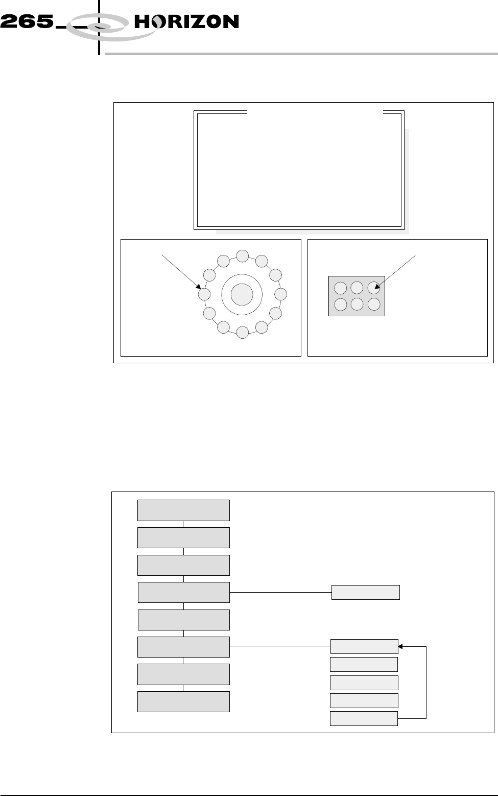
For the green camera the lighting parameters and their functions are shown
below.
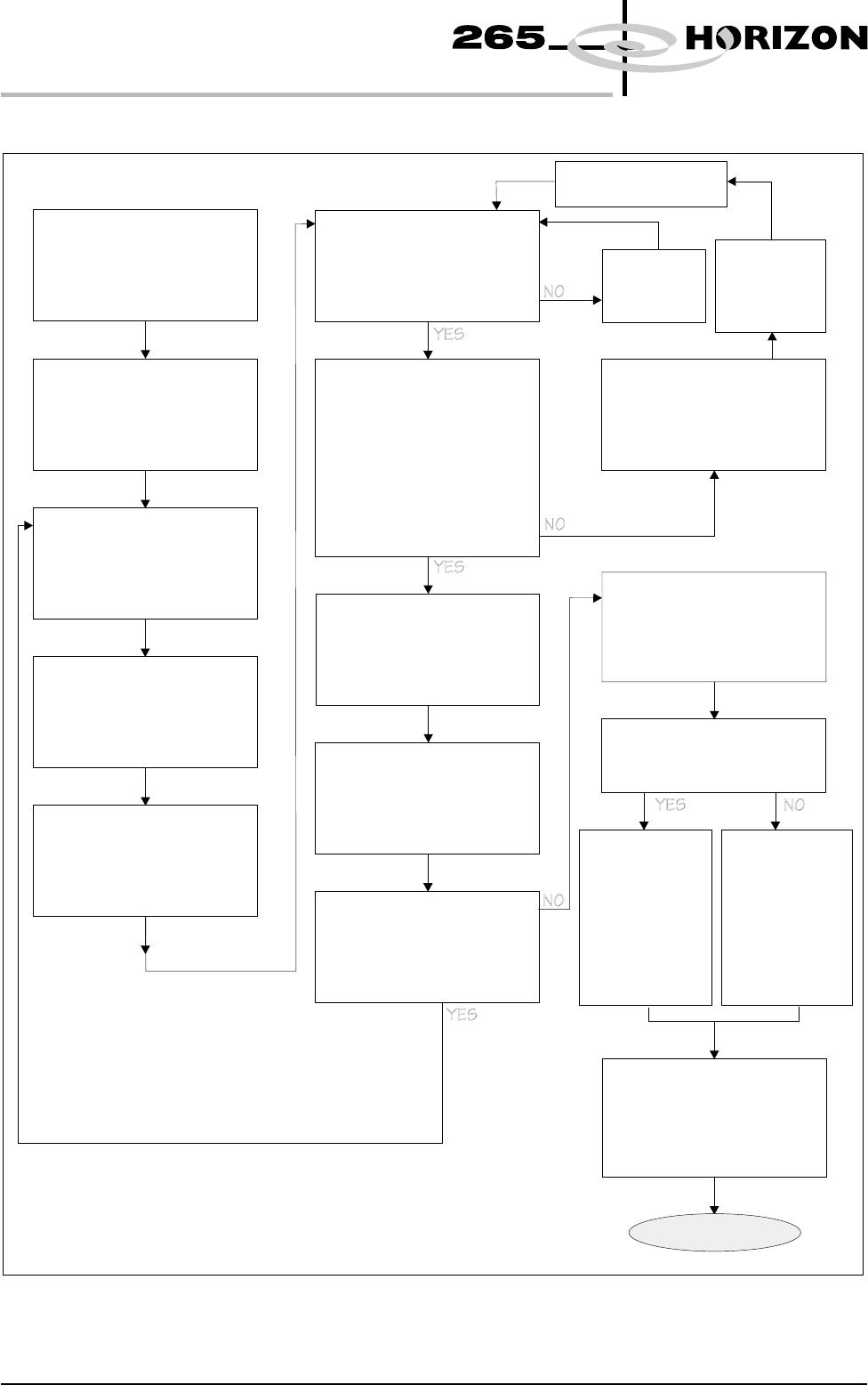
Inspection Setup Correct inspection setup is the key to effective inspection. By following the
steps of the setup sequence, shown in the summary below and the setup guide
over the page, effective inspection may be achieved.
Software Version 6 User Manual 8.11
2Di INSPECTION
MODULE OVERVIEW
8
8
8
8
-1.0
-1.5
2.0
2.0
Inspection Lighting Parameters
Screen Vertical
Screen Oblique
Board Vertical
Board Oblique
Window Left
Window Top
Window Width
Window Height
Oblique Lighting LED
Board and Screen Oblique Lighting
Direct Lighting LED
Board and Screen Direct Lighting
Figure 8-11 Software Controlled Lighting - Green Camera
Setup
Set Preferences
Edit Data
Load Product File
Inspect Setup
Edit Global
Edit Limits
Run
Inspect
Edit Site
Limit Options
Add Site
Learn Site
Learn Board
Auto Learn
Light Setup
Figure 8-12 Summary of Setup
8.12 User Manual Software Version 6
2Di INSPECTION
MODULE OVERVIEW
Adjust Lighting:
Adjust so all board pads are
white with sharp edges and
the screen is seen clearly.
Add Limits Sets:
Set wide tolerances so no
alarms occur.
Add Site:
Name, Location Etc
Ensure all pads are within
the search box.
Set Globals as required:
2D Inspect Rate = 0
Learn Site / Learn Board:
Adjust board graphic ‘X’
and ‘Y’ accurately
Exit out
Auto Scale:
Determine the print closest
to 100% and auto scale on
that pad
Inspect Site:
Paste present data for all
pads are close to the same
value ?
If Board Inspect Type set to
Advance, all the paste
toggles white or yellow on
the board ?
More Sites to Teach ?
Add the rest of the sites
using the same light
settings as this first one
Print Board:
Step through the cycle until
a board is printed.
Is it a good print ?
Exit out
Place a clean
board into the
machine.
Clean screen
Re-adjust Lighting:
Adjust the LED’s to balance
the lighting
Run Product:
Have QC Calc ?
Reset the Globals:
Set the min sites/cycle.
Set 2D Inspect Rate.
Re-adjust the Limit Sets:
The customer may have to
adjust these settings a few
times until the proper
values are found.
SPC Data:
Collect SPC
data on the
2Di. From
this data
derive the
proper ‘limit
sets’ settings.
Trial & Error:
Increase the
‘limit sets’ and
use the data
when it alarms
to derive the
proper
settings.
DONE
New Pre-image taken
Figure 8-13 2Di Inspection Setup Guide