Horizon UserManualV6.pdf - 第275页
10. Set site X coord and site Y coord, using the Next, Previous, Incr. and Decr. keys, to display the site on the monitor. Adjust site width, site height, screen grahic (if applicable), site X coord, and site Y coord, us…
4. Enter parameters using the Next, Previous, Incr. and Decr. keys.
Learn
Site
Light
Setup
Next Previous Incr. Decr.
Exit
5. Highlight site limit ID using the Next and Previous keys.
Learn
Site
Light
Setup
Next Previous
Incr. Decr. Exit
6. Select Incr.
Learn
Site
Light
Setup
Next Previous
Incr.
Decr. Exit
7. Using Next Limit or Previous Limit keys, highlight the coarse limit set
created in either add limits or edit limits.
Use
Limit
Next
Limit
Previous
Limit
Exit
8. Select Use Limit.
Use
Limit
Next
Limit
Previous
Limit
Exit
9. Measure the X and Y dimensions of the required site from the board or
screen.
NOTE
For the initial setup of 2Di use a single site. After the setup is complete add auto
learn features if required.
8.24 User Manual Software Version 6
2Di INSPECTION
2Di SETUP
DEFAULT
FINE
COARSE
Limit Sets
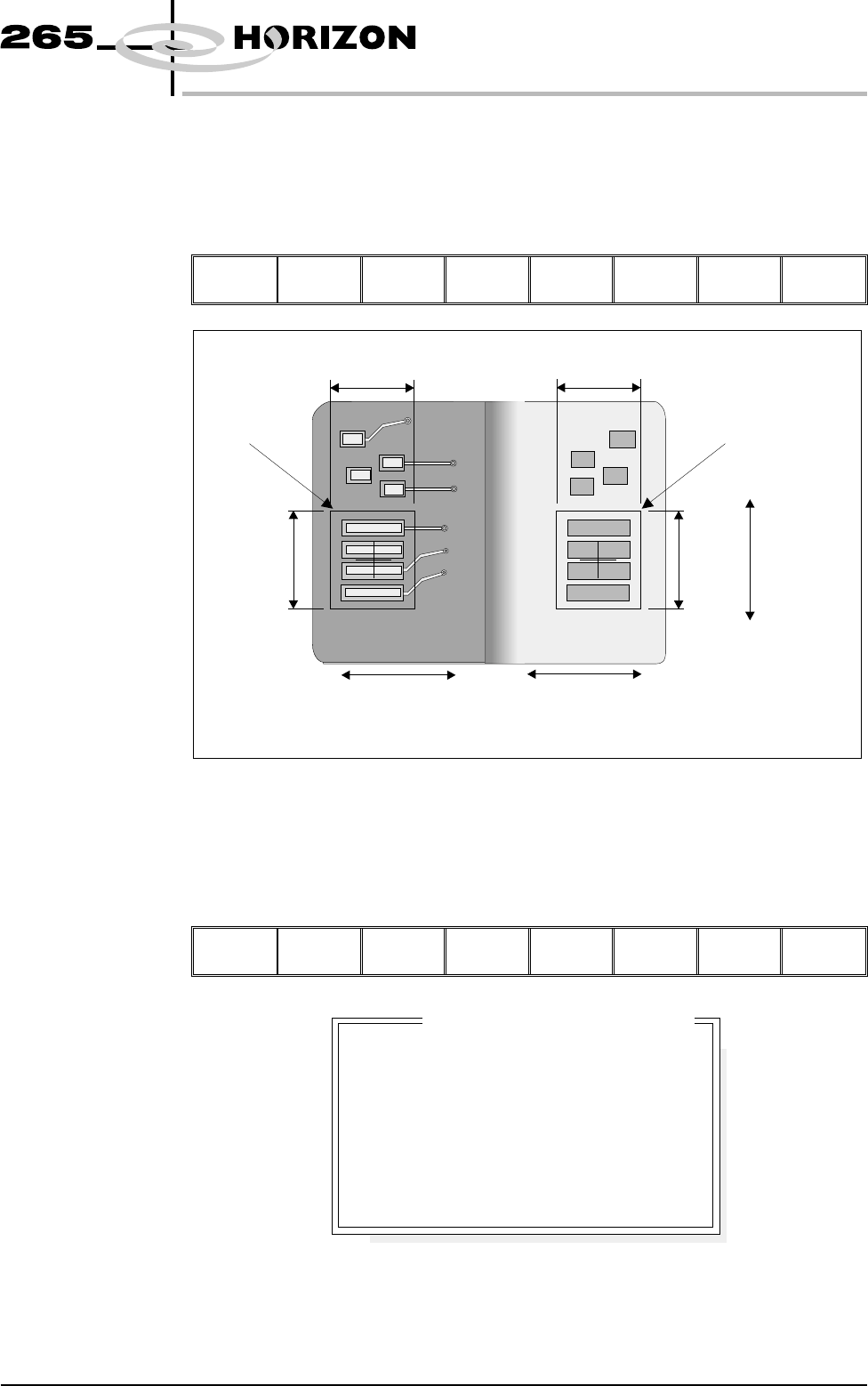
10. Set site X coord and site Y coord, using the Next, Previous, Incr. and Decr.
keys, to display the site on the monitor. Adjust site width, site height, screen
grahic (if applicable), site X coord, and site Y coord, using the Next,
Previous, Incr. and Decr. keys, to position the site graphic over the screen,
as shown.
Learn
Site
Light
Setup
Next Previous Incr. Decr.
Exit
NOTE
Adjust the site height and site width so that the board site is large enough to
cover the pads.
Lighting Setup 1. Select Light Setup.
Learn
Site
Light
Setup
Next Previous Incr. Decr. Exit
Software Version 6 User Manual 8.25
2Di INSPECTION
2Di SETUP
Screen Site
Board Site
Site
Height
Site
Height
Site
Width
Site
Width
Site
Y Coord
Movement
Site
X Coord
Movement
Site
X Coord
Movement
8
8
8
8
-1.5
-1.5
3.0
3.0
mm
mm
mm
mm
Inspection Lighting Parameters
Screen Vertical
Screen Oblique
Board Vertical
Board Oblique
Window Left
Window Top
Window Width
Window Height
Figure 8-14 Lighting Parameters - Green Camera
2. Using the Next, Previous, Incr. and Decr. keys, adjust the lighting
parameters to a level whereby the screen and board pads are just whiting out,
without blooming, default level 8 is usually adequate for the majority of
setups.
Next Previous Incr. Decr.
Exit
3. For machines with a green camera go to Step 6. For machines with a silver
camera continue with Step 4.
4. Adjust the set light graphic using the window left, window top, window
width and window height parameters to surround the feature providing 50%
black and 50% white.
8.26 User Manual Software Version 6
2Di INSPECTION
2Di SETUP
8
8
8
8
8
8
8
8
8
8
-1.0
-1.5
2.0
2.0
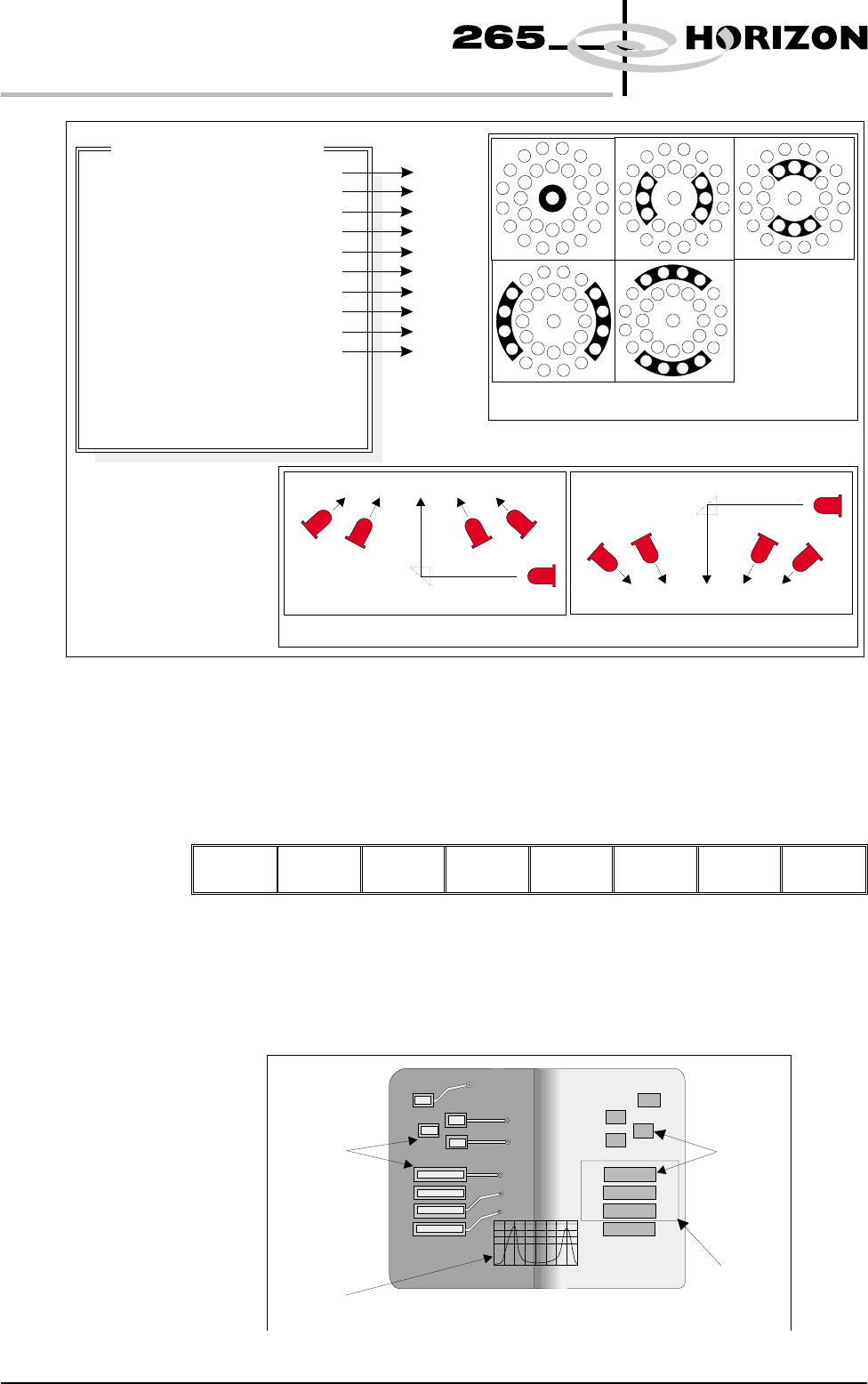
Inspection Lighting Parameters
Screen Vertical
Screen Inner LR
Screen Inner FR
Screen Outer LR
Screen Outer FR
Board Vertical
Board Inner LR
Board Inner FR
Board Outer LR
Board Outer FR
Window Left
Window Top
Window Width
Window Height
A
B
C
D
E
A
B
C
D
E
NOTE
LR = Left and Right
FR=FrontandRear
Camera Lighting
Plan View Figure:
Screen Camera Lighting (Side View)
Prism
Outer
Inner
Inner
Vertical
Outer
LED
Board Camera Lighting (Side View)
Outer
Inner
Vertical
Inner
Outer
Prism
LED
Plan View of Camera Lighting LEDs
(Board or Screen)
A
B
C
D
E
Figure 8-15 Lighting Parameters - Silver Camera
Aperture
Board Pad
Set Light
Graphic
Underside of Screen
Histogram
Top of Board