Horizon UserManualV6.pdf - 第278页
5. Select Exit . Learn Board ReLearn Screen Auto Learn Next Previous Incr. Decr. Exit 6. Select Exit . Add Site Learn Site Light Setup Next Previous Incr. Decr. Exit 8.28 User Manual Software Version 6 2Di INSPECTION 2Di…
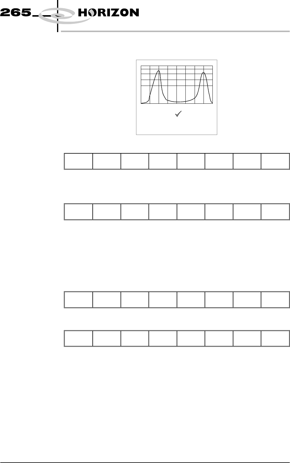
5. Ensure the lighting histogram has a good definition of grey scale levels, as
shown below.
6. Select Exit.
Next Previous Incr. Decr.
Exit
Learn Site 1. Select Learn Site.
Add
Site
Learn
Site
Light
Setup
Next Previous Incr. Decr. Exit
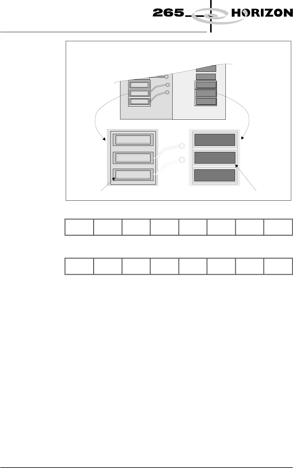
Dependent upon the 2D inspect type selected, the ‘Screen Learnt’ message is
displayed in the message prompt bar above the menu bar. The apertures within
the site are enclosed by individual graphic boxes, as shown over the page. If
‘....Screen Not Learnt’ is displayed, adjust the site parameters and re-learn the
site.
2. Using the Next, Previous, Incr. and Decr. keys adjust the board graphic X
and board graphic Y coordinates to achieve graphic alignment on the board.
Learn
Board
ReLearn
Screen
Auto
Learn
Next Previous Incr. Decr.
Exit
3. Select Learn Board.
Learn
Board
ReLearn
Screen
Auto
Learn
Next Previous Incr. Decr. Exit
4. The message ‘Board Learnt’ is displayed in the message prompt bar above
the menu bar. If ‘....Board Not Learnt’ is displayed, edit the site parameters
and re-learn the site.
NOTE
1. If the size of the graphic box for the site is altered, the screen has to be
re-learnt and this step repeated.
2. Exiting without learning, loses the edited information.
3. The number of pads must equal the number of apertures for a successful site.
4. Adjust the board graphic X and board graphic Y accurately, as this is used as
a reference for alignment measurements.
Software Version 6 User Manual 8.27
2Di INSPECTION
2Di SETUP
Lighting parameters correctly set
5. Select Exit.
Learn
Board
ReLearn
Screen
Auto
Learn
Next Previous Incr. Decr.
Exit
6. Select Exit.
Add
Site
Learn
Site
Light
Setup
Next Previous Incr. Decr.
Exit
8.28 User Manual Software Version 6
2Di INSPECTION
2Di SETUP
The site learnt graphics appear around the screen aperture and on the board pads
confirming that the site is learnt. If necessary, adjust the mirror image board site
graphic over the corresponding pad.
Screen site learnt boxBoard site learnt box
Inspect 1. Select Inspect Site.
Edit
Global
Edit
Limits
Delete
Site
Next
Site
Previous
Site
Edit
Site
Inspect
Site
Exit
NOTE
Delete site,next site and previous site may not be displayed if other sites do not
exist.
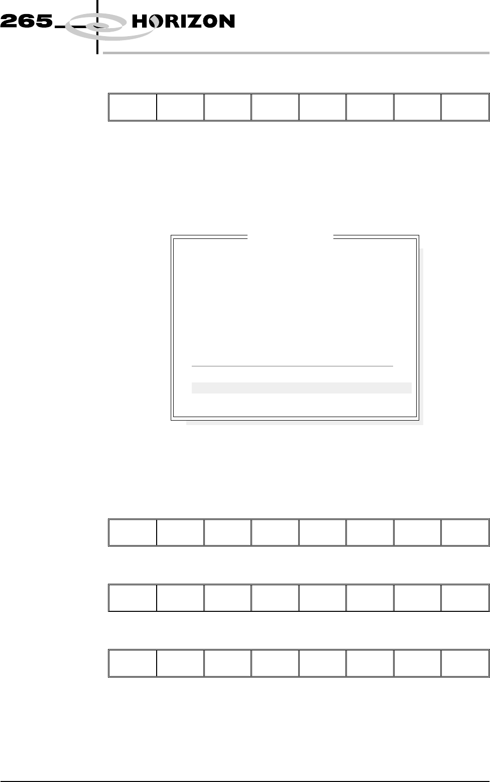
The following window is displayed:
2. If the screen and board were clean, the maximum blockage, smear area and
minimum paste should all be zero. If readings are incorrect, repeat from
Lighting Setup and re-inspect.
3. Select Exit.
Auto
Scale
Toggle
Paste
Next Previous Save
Image
Exit
4. Select Exit.
Edit
Global
Edit
Limit
Delete
Site
Edit
Site
Inspect
Site
Exit
5. Select Step until the board is printed.
Step
Inspect
Setup
Single Exit
Software Version 6 User Manual 8.29
2Di INSPECTION
2Di SETUP
SITE NAME
Maximum Blockage
Smear Area
Minimum Paste
X Alignment
Y Alignment
Bridging
Minimum Paste Volume
Bridge Warnings
Bridge Alarms
SITE 1
0%
0.0 sq mm
0%
----
----
+10.00mm
0%
0
0
Inspection Results
PASS
PASS
ALARM
INVALID
INVALID
PASS
ALARM
No. Blockage Paste Present Volume AlignX AlignY
1 0% 0% 0% ---- ----
2 0% 0% 0% ---- ----