Horizon UserManualV6.pdf - 第71页
8. Remove the stencil from the printer. 9. Close the front printhead cover. 10. Press the System button. 11. Select Change Tooling (F6). Mode Load Data Edit Data Setup Squeegee Change Screen Change Tooling Change Languag…
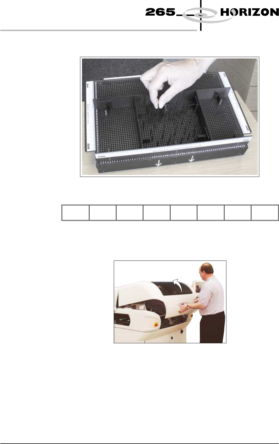
5. Using the grid co-ordinates marked on the template, position pins which
coincide with gaps between the underside board components.
6. Select Change Screen (F5).
Mode Load
Data
Edit
Data
Setup
Squeegee
Change
Screen
Change
Tooling
Change
Language
Exit
The message ‘Open Front Cover and Remove Screen’ is displayed.
7. Open the front printhead cover.
1.54 User Manual Software Version 6
MACHINE PROGRAMMING
STAGE 5D
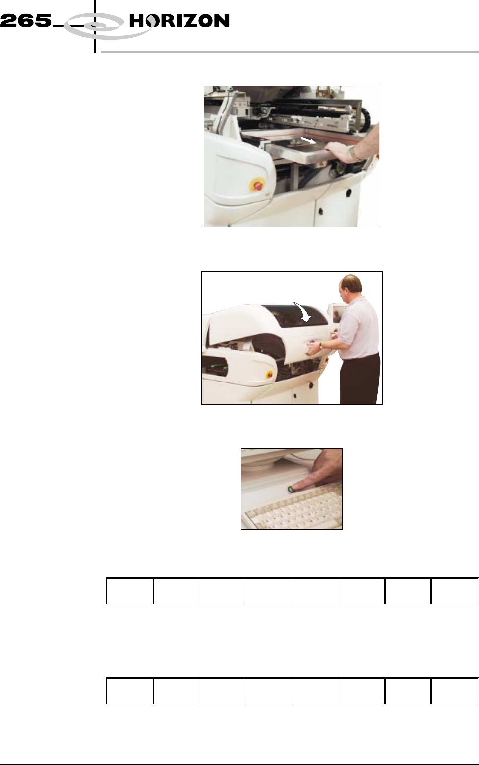
8. Remove the stencil from the printer.
9. Close the front printhead cover.
10. Press the System button.
11. Select Change Tooling (F6).
Mode Load
Data
Edit
Data
Setup
Squeegee
Change
Screen
Change
Tooling
Change
Language
Exit
The print carriage and the under screen cleaner are moved to the rear.
12. Select Full Width (F5).
Adjust Open
Cover
Home
Cleaner
Board
Stop
Full
Width
Load
Width
Print
Height
Exit
The message ‘Checking for a board on the belts’ is displayed. Whilst the rear
rail is moving the following message ‘Rail moving...’ is displayed.
Software Version 6 User Manual 1.55
MACHINE PROGRAMMING
STAGE 5D
13. Select Open Cover (F2).
Adjust
Open
Cover
Home
Cleaner
Board
Stop
Full
Width
Load
Width
Print
Height
Exit
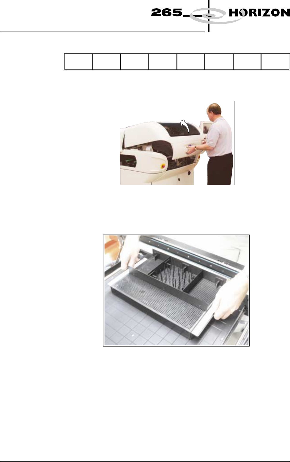
14. Open the front printhead cover.
15. The MultiFlex tooling can now be fitted into the appropriate location holes in
the tooling plate. Ensure that the tooling is placed into the correct set of
holes, taking regard of the type of screen being used and hence the position
of the fixed rail.
1.56 User Manual Software Version 6
MACHINE PROGRAMMING
STAGE 5D