M2series_ServiceManual_e.pdf - 第40页
3 Mechanical Section 3-8 ④ Checking the nozzle for clogging With nozzles placed in the head, tu rn ON the suction to check the air pressure. “Nozzle clog criteria” has been set for each nozzle. The air pressure must be b…
3 Mechanical Section
3-7
■ Checking by Vacuum Meter
Instead of using the machine’s air pressure measurement function, a digital vacuum meter can be used to
check the head’s maximum air pressure as well as that of the head and nozzle for clogging.
ACTION:
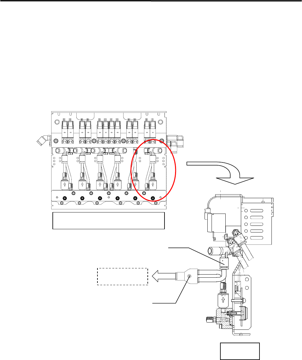
①Connecting a vacuum meter
Remove the air hose from the joint at the vacuum generator side, attach a branch joint and connect the
vacuum meter as shown below.
Branch joint
Joint (at the vacuum generator side)
Side View
Head Manifold Section(Front View)
Vacuum meter
②Checking the maximum air pressure
Turn ON the suction and press the head tip with fingers to check the air pressure. The air pressure is
satisfactory if it is “0.08” MPa or higher.
③Checking the head for clogging
With no nozzles placed in the head, turn ON the suction to check the air pressure. Typical air pressure is
approx. “0.0093” MPa. An error will occur if the air pressure is “0.024” MPa or higher during vacuum
check performed after nozzle replacement.
3 Mechanical Section
3-8
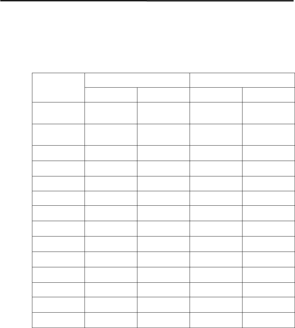
④Checking the nozzle for clogging
With nozzles placed in the head, turn ON the suction to check the air pressure. “Nozzle clog criteria” has
been set for each nozzle. The air pressure must be below the criteria. If it is not, the nozzle will be
considered to be clogged and an error will occur. (The “standard open value” given in the table below is
obtained from measurement of the open value of each nozzle (brand new nozzle) and must be used as a
reference.)
Standard open value (reference) Nozzle clog criteria
Nozzle type
(mmHg) (MPa) (mmHg) (MPa)
N001
N031
590~630 0.077~0.084
640 0.085
N002
N032
430~520 0.063~0.068
540 0.069
N003
285~335 0.043~0.048
420 0.056
N004
70~90 0.009~0.012
350 0.047
N005 40 or less 0.0053 or less 300 0.040
N006 40 or less 0.0053 or less 300 0.040
N012
240~265 0.032~0.035
270 0.036
N013
65~85 0.009~0.011
270 0.036
N017
380~410 0.051~0.055
470 0.063
N018
70~90 0.009~0.012
300 0.040
N019
70~90 0.009~0.012
300 0.040
N020 40 or less 0.0053 or less 300 0.040
N021
430~520 0.063~0.068
540 0.069
N022
430~520 0.063~0.068
540 0.069
NOTE: 1mmHg=133.322Pa=0.00013332MPa
3 Mechanical Section
3-9
Nozzle
When obstacles such as solder paste are stuffed up in the nozzle, the suction becomes weak. And existence
of an obstacle at the nozzle tip prevents the vision processing from recognizing smaller components. Clean
nozzles to avoid these troubles.
■ Nozzle Cleaning with Air Blow
Clean the nozzle tips with alcohol and then blow away dust with a blower (more than once a week). When
choking error occurs, also do the cleaning of the nozzle.
Be careful not to apply alcohol to identification marks. Quickly wipe off if
applied.
■ Nozzle Cleaning using Wire (1)
Normally, cleaning with the air blow may be enough. But when the dirt is firmly fixed, clean the nozzle
using a wire.
NOTE: To clean the nozzle using a wire, the O-ring and the nozzle filter inside the nozzle must be removed first.
Cleaning the nozzle with a wire without removing them may result in the damage or loss of them. After the
nozzle is cleaned, make sure to re-install them using a special tool.
NOTE: For a description of how to remove/install the O-ring and nozzle filter, refer to “Removing O-ring and
Nozzle filter” and “Attaching O-ring and Nozzle filter” given later in this manual.
Take care not to get injured with the fine wire when cleaning the nozzle.
ACTION:
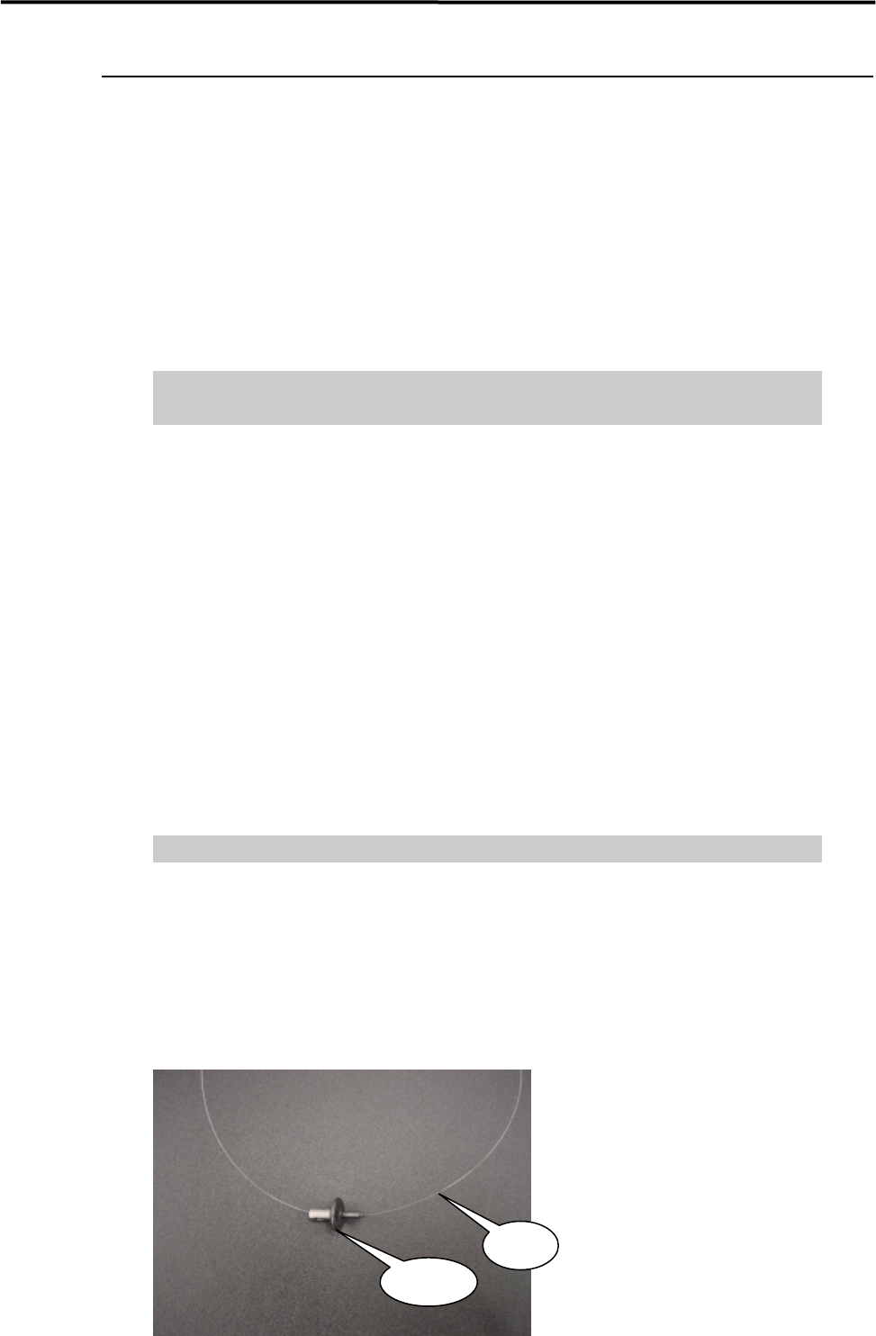
① Have a wire ready.
(300mm length, 0.1mm diam. Part No. KV8-M8887-00X)
② Remove the O-ring and nozzle filter from the nozzle.
③ Pass the wire through the nozzle hole.
Wire
Nozzle