M2series_ServiceManual_e.pdf - 第45页
3 Mechanical Section 3-13 ■ O-ring If the O-ring inside the n ozzle deteriorates and dev elops cracks, air leakage will occur. This will reduce the maxim um air pressure (negative pressure), causing pr oblem s with sucti…
3 Mechanical Section
3-12
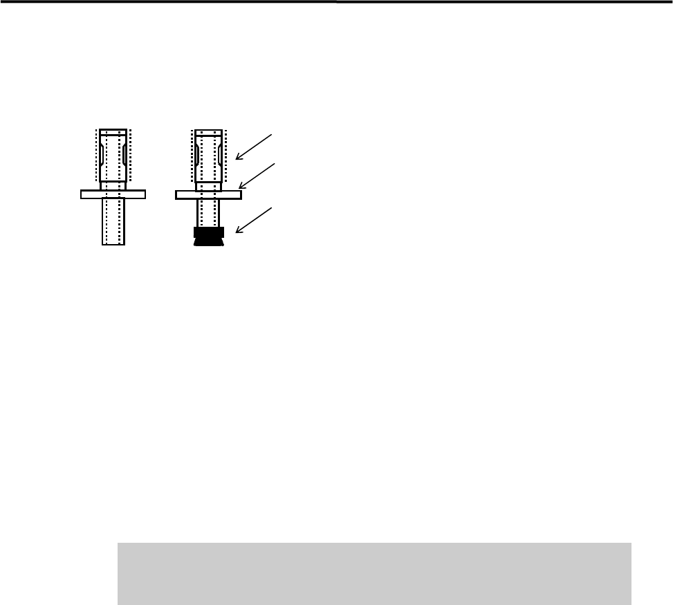
■ Applying Silicon Grease
After the nozzle is cleaned, it must be coated with silicon grease.
Apply silicon grease.
Nozzle ID sticker
Suction pad
● Nozzle outer surface
Apply a slight amount of grease to the outer surface (indicated by dotted lines in the above illustration), and
then wipe it off with a dry cloth.
NOTE: Silicon grease must be applied so that it forms a thin film on the surface.
● Suction pad
Application of oil content is needed to prevent deterioration of the rubber. Apply a slight amount of grease
to the outer surface of the suction pad, and then wipe it off with a dry cloth.
NOTE: Silicon grease must be applied so that it forms a thin film on the surface.
Do not apply excessive amounts of grease. This may cause collection of dirt
or dust in the air passage and on placed components, resulting in component
placement failure.
● Checking the nozzle escape
After grease is applied to the nozzle’s outer surface, attach the nozzle to the head and check the condition of
the nozzle escape.
NOTE: When the nozzle is placed in the head (nozzle holder), it can slide a few millimeters vertically. This nozzle
sliding movement is called nozzle escape.
ACTION:
① Attach the nozzle to the head.
② Push the nozzle gently with fingers up to the top dead center of the nozzle escape.
③ Release fingers gently and check that the nozzle returns to the lower dead center smoothly.
NOTE: If the nozzle escape is not smooth, there may be problems with component suction and placement. If the
nozzle gets caught or does not move smoothly, check the nozzle holder and nozzle’s inner/outer surfaces
for collection of foreign matter or scratches.
3 Mechanical Section
3-13
■ O-ring
If the O-ring inside the nozzle deteriorates and develops cracks, air leakage will occur. This will reduce the
maximum air pressure (negative pressure), causing problems with suction operation. If the reduction in the
maximum air pressure is found and the cause seems to be in the nozzle, replace the O-ring inside the nozzle.
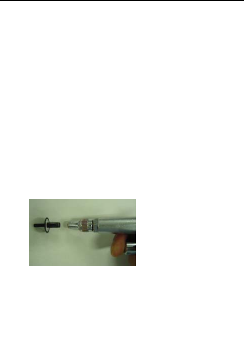
ACTION:
① Pull out the O-ring from the nozzle and clean inside the nozzle with an air blower.
② Insert a new O-ring into the nozzle from its rear end.
③ Push the O-ring against the bottom inside the nozzle.
④ After the new O-ring has been set in place, attach the nozzle to the head and check for nozzle
clogging.
)
Checking the nozzle for clogging
NOTE: Do not apply silicon grease or the like to the O-ring since it may cause nozzle clogging.
■ Nozzle Filter
The nozzle filter prevents dust from getting inside the nozzle. It also prevents the escape action malfunction
caused by the dust. Periodical cleaning of the nozzle filter must be performed.
ACTION:
① Clean the nozzle with an air blower from its rear end.
NOTE: Normally, cleaning with the air blow may be enough. But when the dirt is firmly fixed, remove the O-ring
and the filter to clean.
NOTE: Nozzles with filter:
N004, N005, N006, N013, N018, N019, N020,
Custom-made nozzles
Part Name
Part No. Remark
O RING LC1-M77A5-90X
FILTER LC1-M771Y-10X
3 Mechanical Section
3-14
REMOVER,O-RING LC1-M861R-01X O-ring removal jig
PIN(O RING) LC1-M8911-10X For inserting O-ring
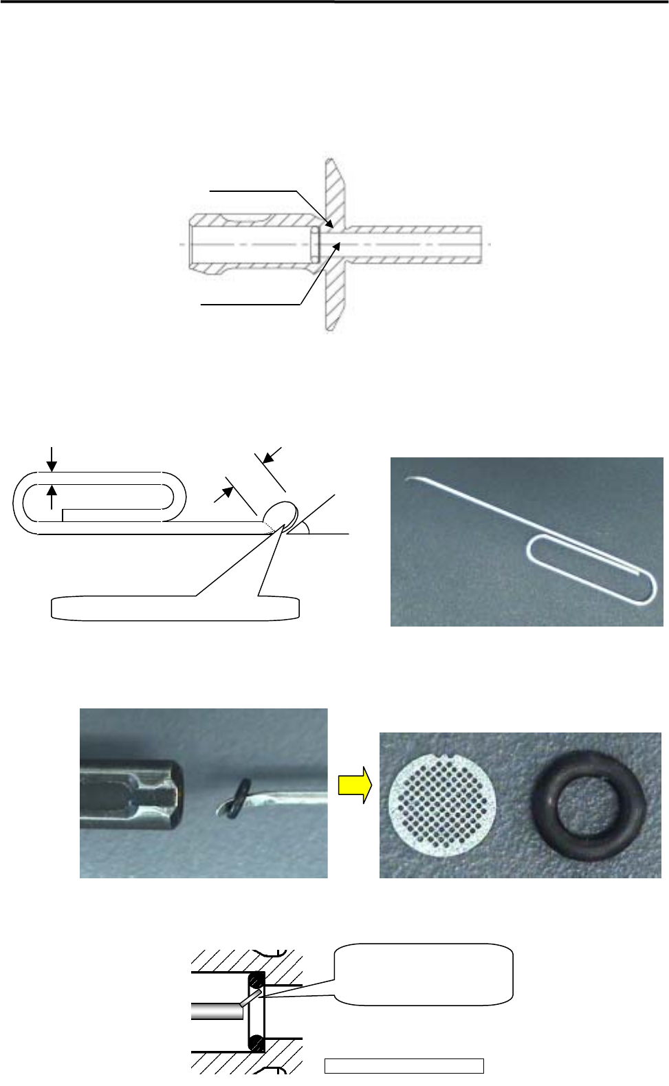
■ Removing O-ring and Nozzle Filter
NOTE: The filter is fixed by the O-ring. It has no right-side up.
Filter
O-ring
ACTION:
① Insert an O-ring removal jig like illustrations below into the nozzle from its rear end.
Jig: Modify a commercially available clip.
Dia.1mm
3mm
30 to 45 degrees
Flatten the pin edge by pliers.
(
t=0.3mm
)
② Insert the pin-edge of the jig between the O-ring and the seating face, and pull it out from the nozzle
(take care not to let the O-ring come off).
Magnified view of O-ring part
Insert the flatten pin-edge between
the O-ring and the seating face.