M2series_ServiceManual_e.pdf - 第60页
3 Mechanical Section 3-28 ■ Applying Grease to R-axis Gear (R-a xis Spline Shaft / Z-axis Ball Screw) ACTION: ① Select [Manual] to displ ay [Nozzle Info] window. From this window, return all t he nozzles to ANC, and move…
3 Mechanical Section
3-27
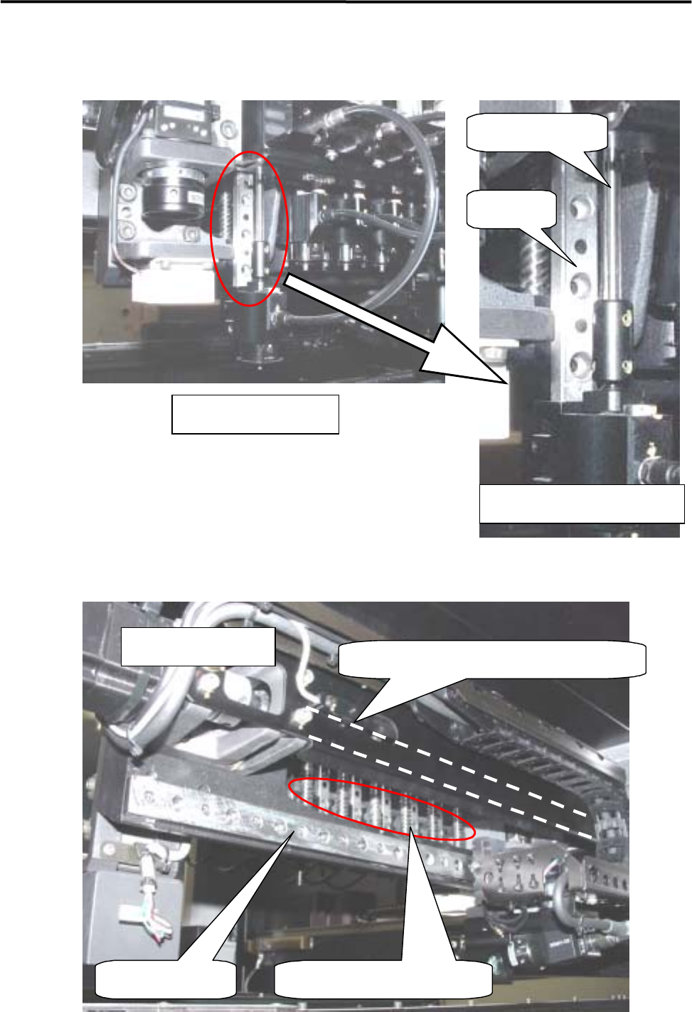
■ Lubrication Points for Z-axis Guide / R-axis Spline Shaft
Head Unit Section
Z-axis unit (enlarged view)
R-axis spline shaft
Z-axis
g
uide
■ Lubrication Points for S-axis / Z-axis Ball Screw
S-axis Linear guide
S-axis ball screw (#1 to #6)
S-axis ball screw (indicated by dotted line)
Rear of head base
3 Mechanical Section
3-28
■ Applying Grease to R-axis Gear (R-axis Spline Shaft / Z-axis Ball Screw)
ACTION:
① Select [Manual] to display [Nozzle Info] window. From this window, return all the nozzles to ANC,
and move the head to the center (X-axis) approximately and to the nearest front side (Y-axis) in JOG
mode.
② Remove the head cover unit. (For the method, refer to “Head Cover Unit”.)
③ Turn OFF the main power of the machine.
④ Lower all the heads approximately to the height of the scan camera by hand. (If they are not lowered,
they will cause an obstruction when the head cover base is opened.)
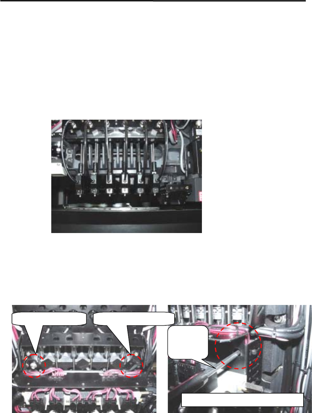
⑤ Loosen the two head cover base fixing screws with a hexagonal wrench.
NOTE: Each fixing screw has an E-ring to prevent the screw from falling. So when loosening/tightening the screws,
turn the E-ring approx. three turns to right and left alternately. If they are turned in one direction only, the
E-ring may deform the head cover base.
Left-side fixing screw Right-side fixing screw
Hexagonal
wrench
Enlarged view of right-side fixing screw
3 Mechanical Section
3-29
⑥ While holding the head cover base by hand, open it slowly. (The cover can be opened at a certain
angle due to the left-side wire.)
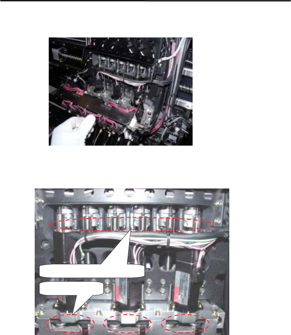
⑦ Apply grease to the R-axis gear (3 points), R-axis spline shaft’s upper section and Z-axis ball screw’s
upper section of each head. Do not apply an excessive amount of grease as doing so may cause grease
splash. (An appropriate amount that forms a film of oil on the gear surface is sufficient.)
R-axis gear (3 points)
R-axis spline shaft, Z-axis ball screw
⑧ To spread the grease over the entire moving area, move the R- and Z-axis by hand. For the R-axis, the
heads having even or odd numbers must be rotated at lease one turn. For the Z-axis, each head must be
moved up and down a few times.
⑨ Install the head cover base in the reverse order of removal.
⑩ Raise all the heads approximately to the height of the machine origin by hand.
⑪ Attach the head cover unit.