M2series_ServiceManual_e.pdf - 第62页
3 Mechanical Section 3-30 ■ Lubrication Points for MX-20 (Opt ion)
3 Mechanical Section
3-29
⑥ While holding the head cover base by hand, open it slowly. (The cover can be opened at a certain
angle due to the left-side wire.)
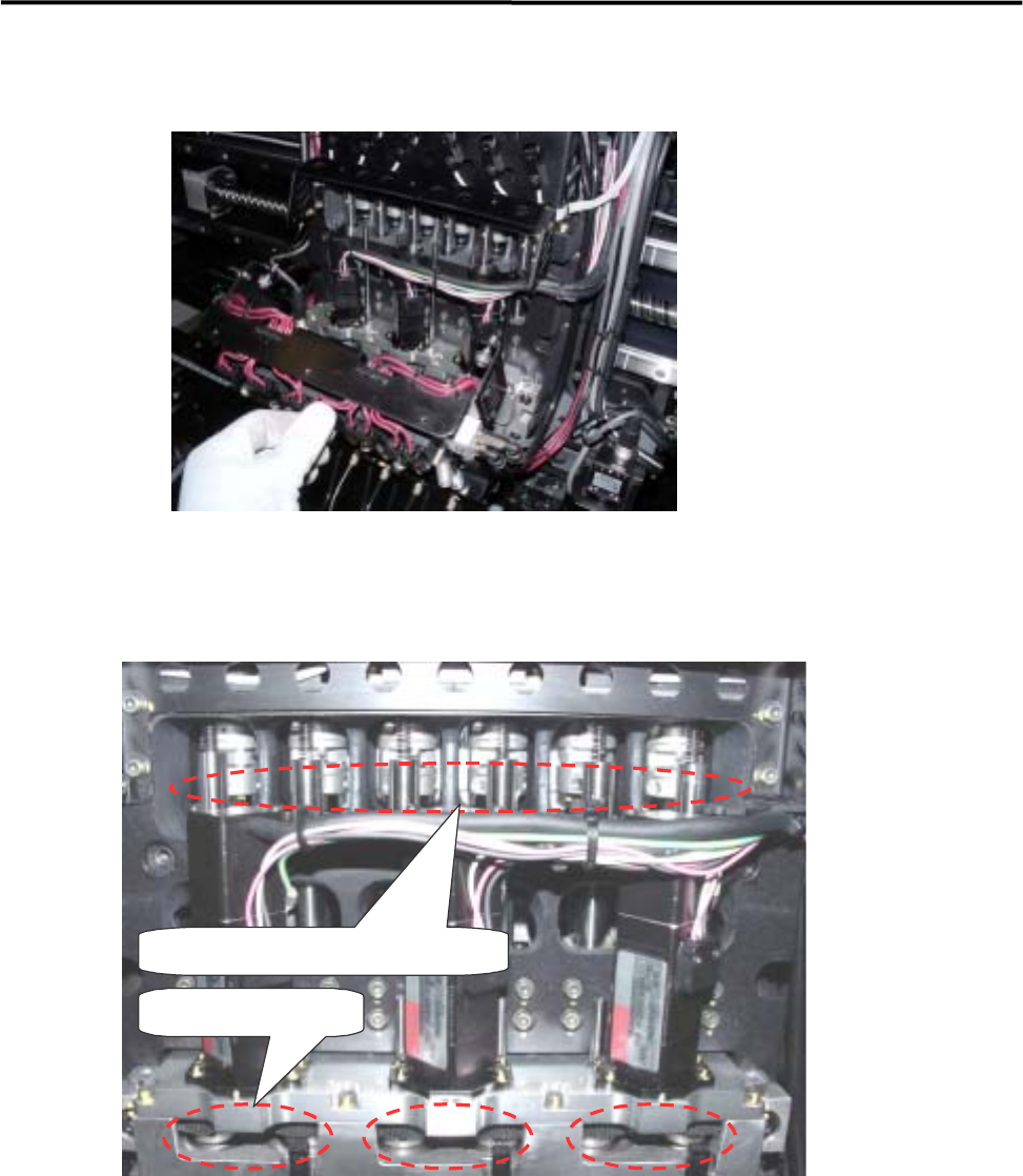
⑦ Apply grease to the R-axis gear (3 points), R-axis spline shaft’s upper section and Z-axis ball screw’s
upper section of each head. Do not apply an excessive amount of grease as doing so may cause grease
splash. (An appropriate amount that forms a film of oil on the gear surface is sufficient.)
R-axis gear (3 points)
R-axis spline shaft, Z-axis ball screw
⑧ To spread the grease over the entire moving area, move the R- and Z-axis by hand. For the R-axis, the
heads having even or odd numbers must be rotated at lease one turn. For the Z-axis, each head must be
moved up and down a few times.
⑨ Install the head cover base in the reverse order of removal.
⑩ Raise all the heads approximately to the height of the machine origin by hand.
⑪ Attach the head cover unit.
3 Mechanical Section
3-30
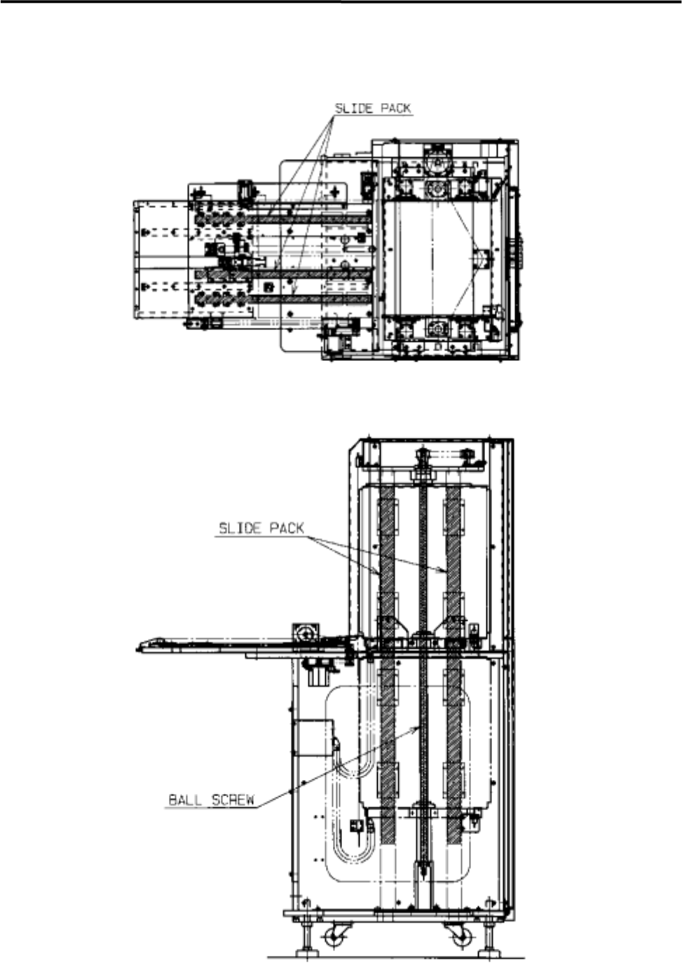
■ Lubrication Points for MX-20 (Option)
3 Mechanical Section
3-31
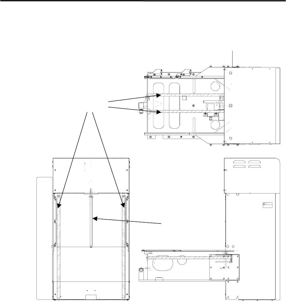
■ Lubrication Points for MXR-20 (Option)
Linear Shaft
Ball Screw