Foreign Machine Interface - 第41页
FOREIGN MACHINE INTERFACE MULTI-INTERFACE UNIT Chapter Issue 3 Jan 08 Technical Reference Manu al 28.41 TDK Interface TDK Schematic TDK Downline TDK Upline TDK FMI Connection - Upline (SW2) and Downline (SW3) T o Positio…
FOREIGN MACHINE INTERFACE
MULTI-INTERFACE UNIT
28.40 Technical Reference Manual Chapter Issue 3 Jan 08
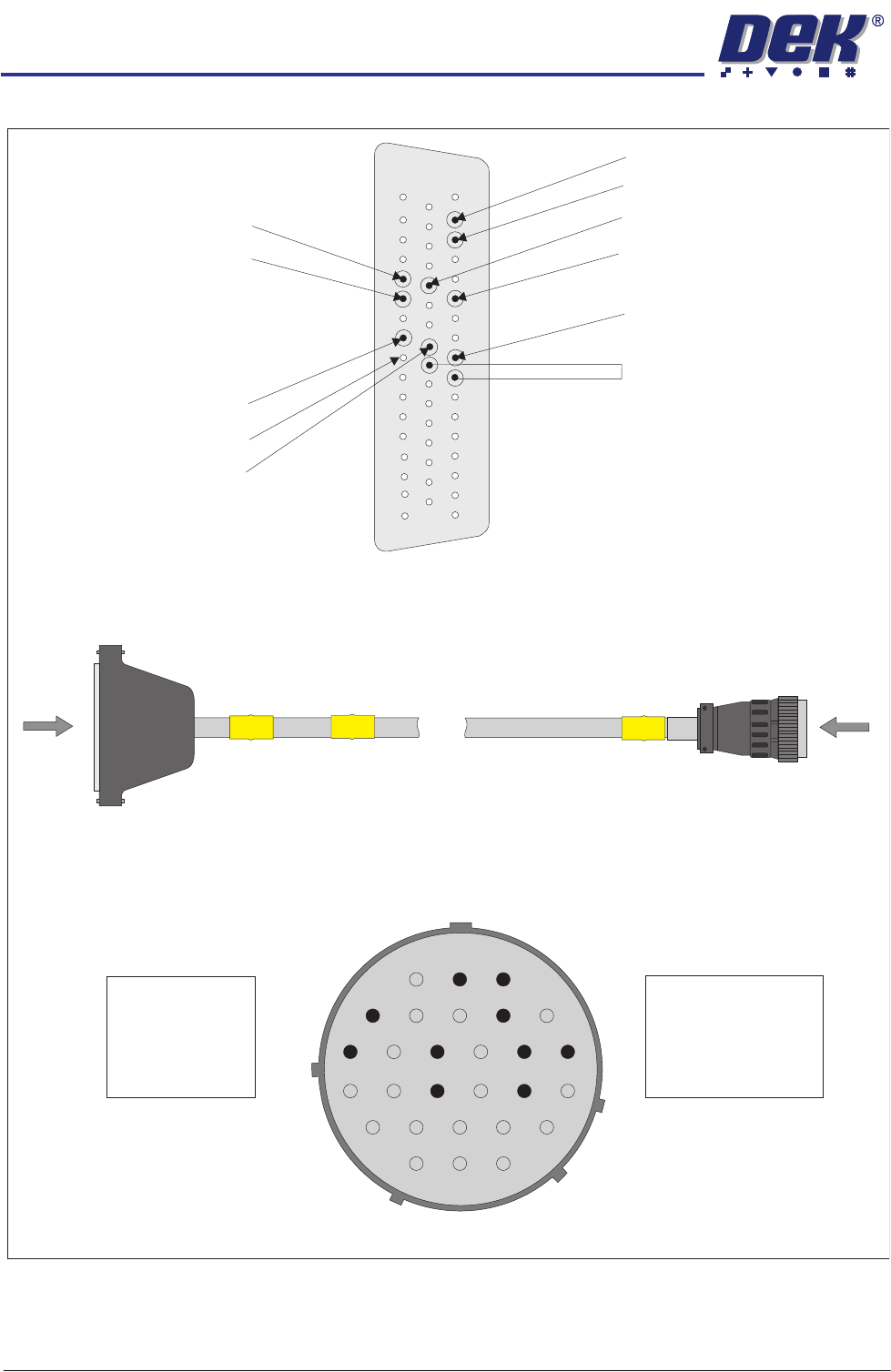
SMPI Downline Interface Cable
View on Arrow B
1
4
9
15
17
11
21
26
3
2
8
7
14
13
20
19
25
28
B
PLY
SMPI Downline Plug
AMP 206039-1
A
PLX
DEK Machine
50 Way D-type
View on Arrow A
Pin 26- Downline TRI
Pin 9- Downline MAI
Pin 42 - Downline ARI
VLED In (+12V) Link
Pin 25 to Pin 41
Pin 45 - Downline ARO
Pin 10 - Downline SRI
Pin 12 - Downline MAO
Pin 13 - Downline SRO
Pin 49 - VLED Out (+12V)
Pin 48 - VLED Out (+12V)
Pin 29 - Downline TRO
33
50
1
18
34
17
Pin 4 - TRO
Pin 2 - RRO
Pin 17 - MAI
Pin 11 - RRI
Pin 9 - VLED In
Pin 3 - ARO
Pin 14 - TRI
Pin 13 - ARI
Pin 7 - MAO
Pin 19 - VLED Out
FOREIGN MACHINE INTERFACE
MULTI-INTERFACE UNIT
Chapter Issue 3 Jan 08 Technical Reference Manual 28.41
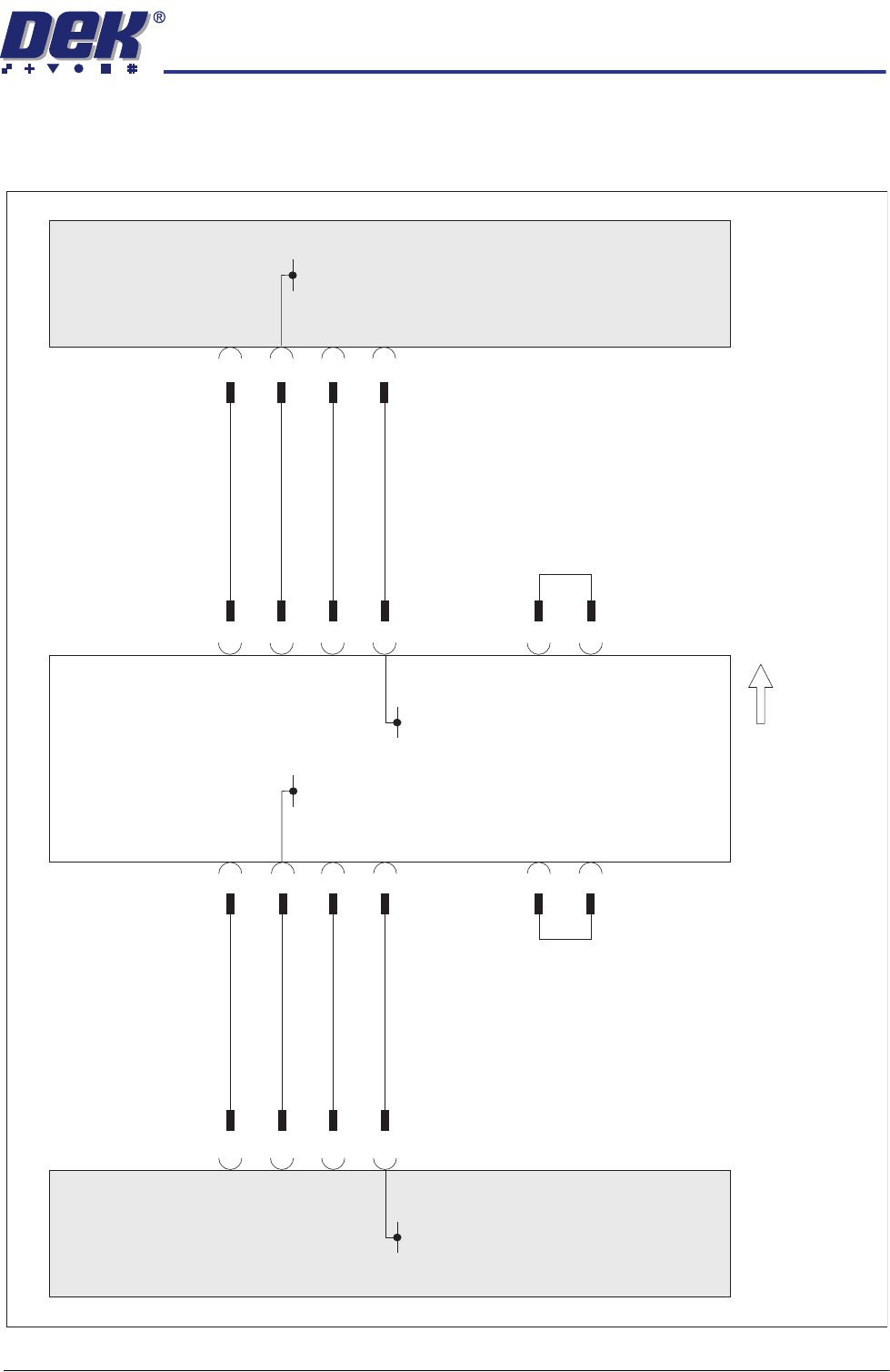
TDK Interface
TDK Schematic
TDK
Downline
TDK
Upline
TDK FMI Connection - Upline (SW2) and Downline (SW3) To Position 5.
JAE
Connector
SCRN6A21-16P
JAE
Connector
SCRN6A21-16P
1
9
Start
2
16
9
Ready
1
17
8
9
Start
9
16
17
Ready
1
1
8
2
DEK
Multi-Interface Unit
Board Direction
Upline
50 Way
D-type
M1SK1
Downline
50 Way
D-type
M1SK2
0V
0V
0V
0V
+24V(A)
15
25
+24V(A)
15
25
FOREIGN MACHINE INTERFACE
MULTI-INTERFACE UNIT
28.42 Technical Reference Manual Chapter Issue 3 Jan 08
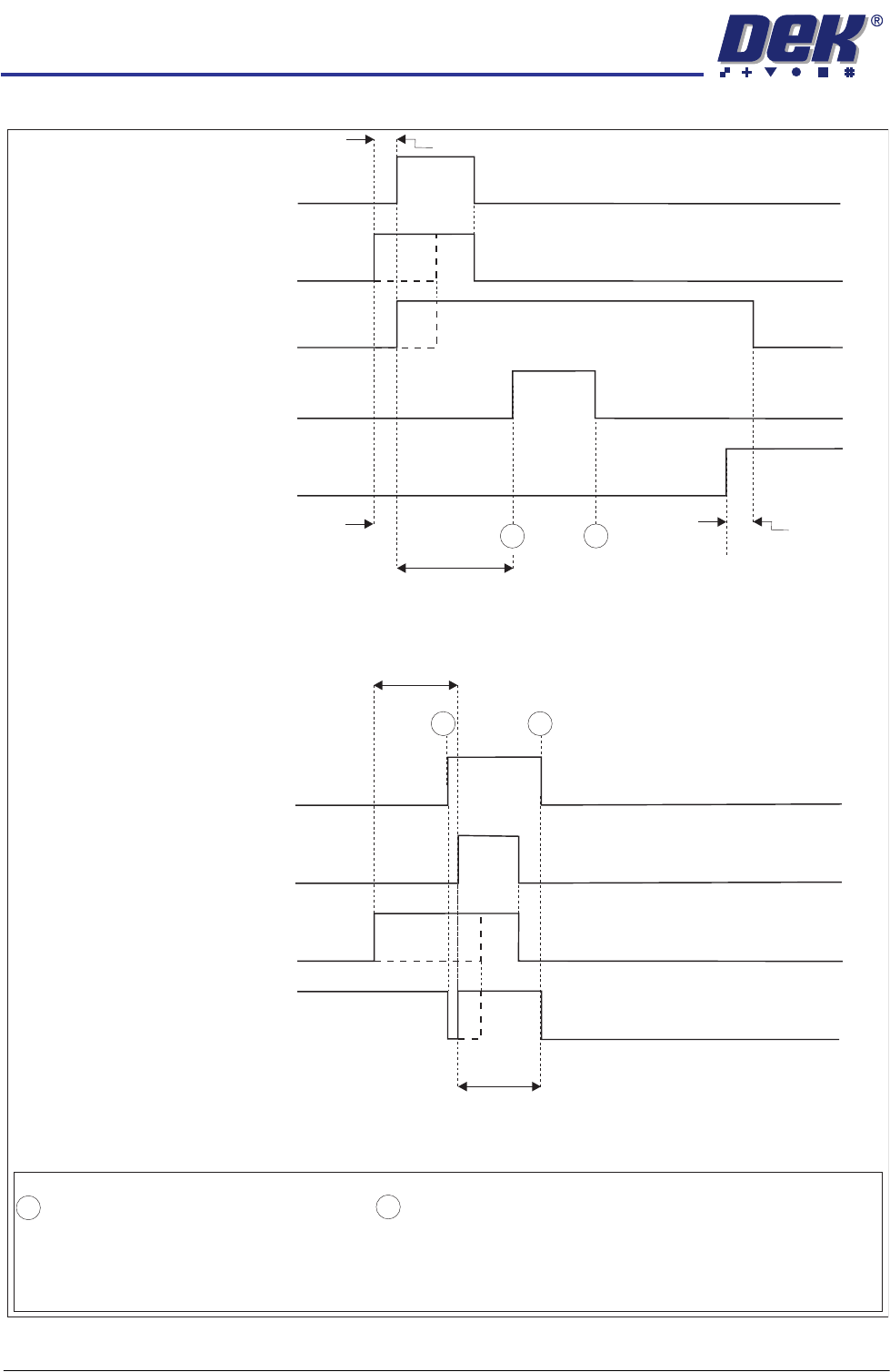
TDK Logical Timing Diagram
DEK M/C Input Sensor
Upline M/C
(I/P to DEK M/C)
Ready
DEK M/C
(O/P from DEK M/C)
Start
DEK M/C Board At Stop Sensor
DEK M/C
Ready
Board At Stop
Transfer Complete
< Transfer Period
< Transfer Period
< Transfer Period
< Transfer Period
Belt Overrun
TDK Upline Logical Timing Diagram
DEK M/C Belts Running
A
NOTES
The 'Ready' and 'Start' signals are independent of each other and either signal may be switched on first (contacts
closed). A board transfer occurs when both the 'Ready' and 'Start' signal are switched on (contacts closed). The
'Ready' and 'Start' signals are switched off (contacts open) 500msecs after both signals are switched on (contacts
closed).
- Board Trailing Edge at Sensor
- Board Leading Edge at Sensor
A
B
TDK Downline Logical Timing Diagram
Downline M/C
(I/P to DEK M/C)
Ready
DEK M/C Belts Running
DEK M/C Output Sensor
DEK M/C
(O/P from DEK M/c)
Start
A
B
B