Foreign Machine Interface - 第5页
FOREIGN MACHINE INTERFACE FMI POD Chapter Issue 3 Jan 08 Technical Reference Manu al 28.5 SMEMA Interface SMEMA Schematic 1 2 3 4 Shield SMEMA Downline 1 2 3 4 14 Shield SMEMA Upline DEK M/C Read y Board Available Board …
FOREIGN MACHINE INTERFACE
FMI POD
28.4 Technical Reference Manual Chapter Issue 3 Jan 08
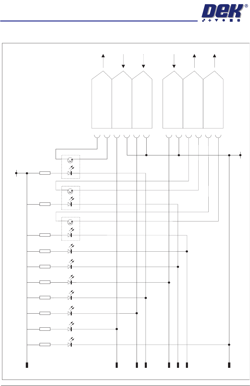
FMI Pod Circuit
+12V
0V
22
18
05
15
09
06
13
07
023
R1
4K7
D1
D3
D4
D5 D6
D7
D2
R2
4K7
R3
4K7
R4
4K7
R5
4K7
R6
4K7
R7
4K7
R8
1K
R9
1K
R10
1K
ICI-A
ICI-B
ICI-C
191
193
126
192
127
128
007
M28PL01
M28SK02
DEK M/C Available
0V Return
0V Return
0V Return
0V Return
0V Return
0V Return
Board Available
Board Pass
Board Pass
Board Available
01
03
04
10
11
16
17
19
21
24
25
02
O/P
O/P
O/P
I/P
I/P
I/P
Downline M/C Available
To Upline M/C
To Downline M/C
FOREIGN MACHINE INTERFACE
FMI POD
Chapter Issue 3 Jan 08 Technical Reference Manual 28.5
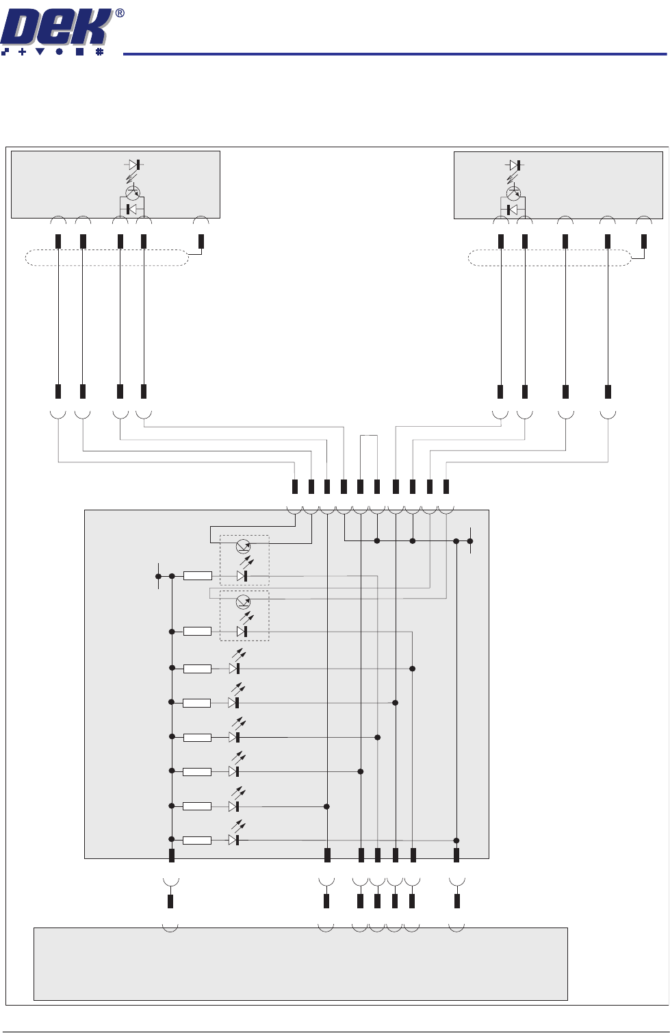
SMEMA Interface
SMEMA Schematic
1
2
3
4
Shield
SMEMA
Downline
1
2
3
4
14
Shield
SMEMA
Upline
DEK M/C Ready
Board Available
Board Available
Downline M/C Ready
0V Return
0V Return
0V Return
0V Return
22
18
05
09
06
07
15
FMI Pod
R9
1K
ICI-B
R10
1K
ICI-C
D2
R2
4K7
D3
R3
4K7
D4
R4
4K7
D1
R1
4K7
D6
R6
4K7
D5
R5
4K7
+12V
01
02
03
04
10
11
16
17
19
21
01
01
02
02
03
03
04
04
14
0V
0V Link
M36SK04
Machine
Controller
Enclosure
22
18
05
15
09
06
07
M28PL01
M28SK02
SK A
SK B
FOREIGN MACHINE INTERFACE
FMI POD
28.6 Technical Reference Manual Chapter Issue 3 Jan 08
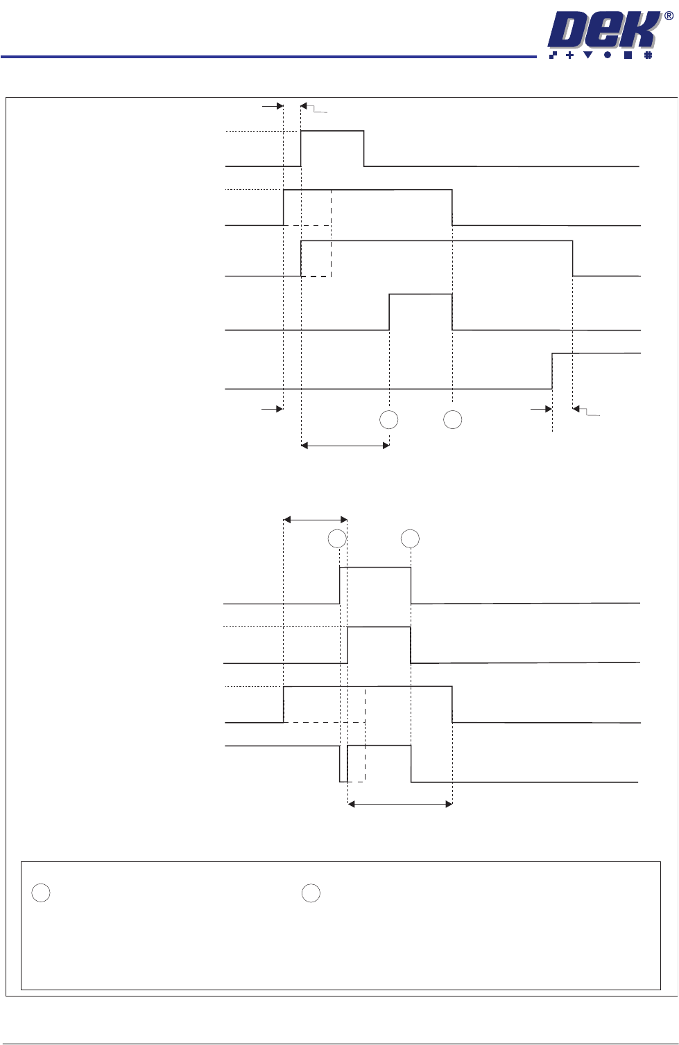
SMEMA Logical Timing Diagram
NOTES
A board transfer occurs when a board is available and the machine is ready.
The Board Available signal and Machine Ready signal can occur at anytime, but board transfer does not occur
until both signals are present.
The Board Available signal is present until the board has left the machine.
The Machine Ready signal is present until the board has arrived at the next machine.
- Board Trailing Edge at Sensor
- Board Leading Edge at Sensor
A
B
SMEMA Downline Logical Timing Diagram
Downline M/C
(I/P to DEK M/C)
Board Not Available
Board Available
DEK M/C Belts Running
DEK M/C Output Sensor
DEK M/C
(O/P from DEK M/C)
Machine Ready
Machine Not Ready
A
B
SMEMA Upline Logical Timing Diagram
DEK M/C Input Sensor
Upline M/C
(I/P to DEK M/C)
Board Not Available
Board Available
DEK M/C
(O/P from DEK M/C)
Machine Ready
Machine Not Ready
DEK M/C Board At Stop Sensor
Board At Stop
Transfer Complete
< Transfer Period
< Transfer Period
< Transfer Period
< Transfer Period
Belt Overrun
DEK M/C Belts Running
A
B
DEK M/C Ready