Foreign Machine Interface - 第53页
FOREIGN MACHINE INTERFACE MULTI-INTERFACE UNIT Chapter Issue 3 Jan 08 Technical Reference Manu al 28.53 Sanyo Interface Sanyo Schematic Sanyo Downline 10W Sanwa Free Plug 10W Sanwa Free Plug Sanyo Upline Ready Sig. PCB T…
FOREIGN MACHINE INTERFACE
MULTI-INTERFACE UNIT
28.52 Technical Reference Manual Chapter Issue 3 Jan 08
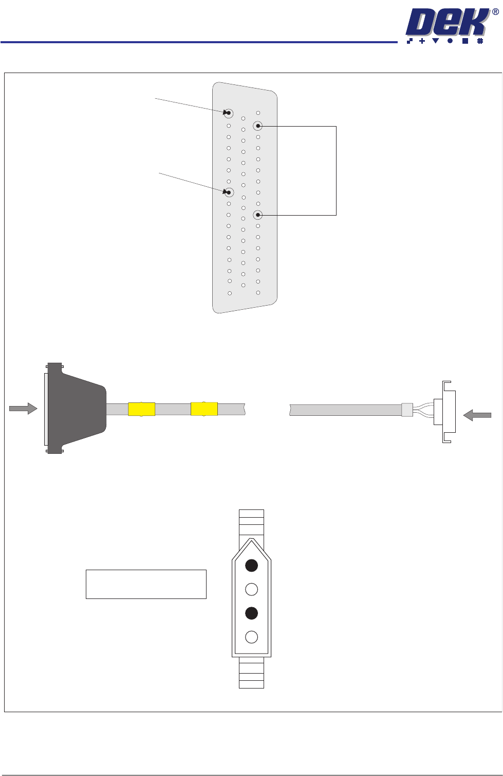
Panasonic Downline Interface Cable
View on Arrow B
B
PLB
Panasonic
Downline Plug
4 Pin Molex
A
PLA
DEK Machine
50 Way D-type
View on Arrow A
+12V Link
Pin 41 to Pin 49
Pin 17 - Board Request (L)
Pin 10 - Board Request (H)
33
50
1
18
34
17
3
1
Pin 1 - Board Request (L)
Pin 3 - Board Request (H)
FOREIGN MACHINE INTERFACE
MULTI-INTERFACE UNIT
Chapter Issue 3 Jan 08 Technical Reference Manual 28.53
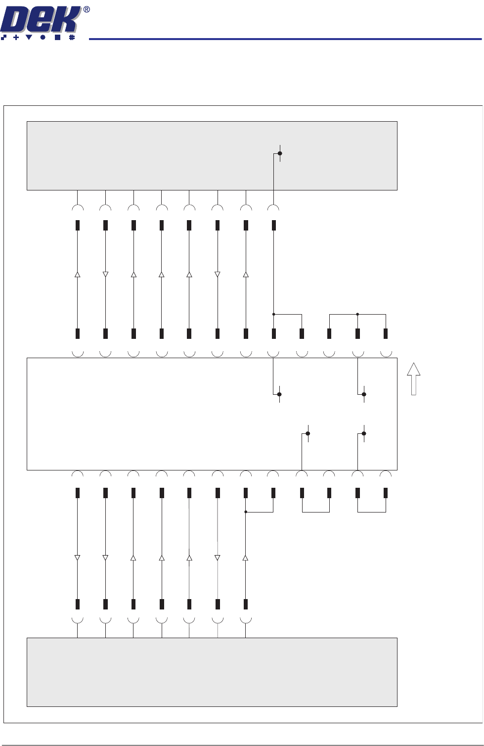
Sanyo Interface
Sanyo Schematic
Sanyo
Downline
10W Sanwa
Free Plug
10W Sanwa
Free Plug
Sanyo
Upline
Ready Sig.
PCB Transfer Sig.
Run Sig.
O/P M/C Run Sig.
O/P M/C PCB Requirement Sig.
5
26
50
35
5
3
3
36
4
34
1
10
9
VLED In
VLED In
15
+24V(A)
+24V(A)
10
17
8
+24V(A)
+24V(A)
41
37
50
35
2
I/P M/C Ready Sig.
I/P M/C PCB Transfer Sig.
I/P M/C Run Sig.
Run Sig.
PCB Requirement Sig.
42
4
Sanyo FMI Connection - Upline (SW2) and Downline (SW3) Positions 8 & 9 Respectively.
37
4
42
3
10
2
1
34
36
9
41
17
8
15
25
DEK
Multi-Interface Unit
Downline
50 Way
D-type
M1SK2
Upline
50 Way
D-type
M1SK1
Board Direction
0V
0V
0V
0V
0V
FOREIGN MACHINE INTERFACE
MULTI-INTERFACE UNIT
28.54 Technical Reference Manual Chapter Issue 3 Jan 08
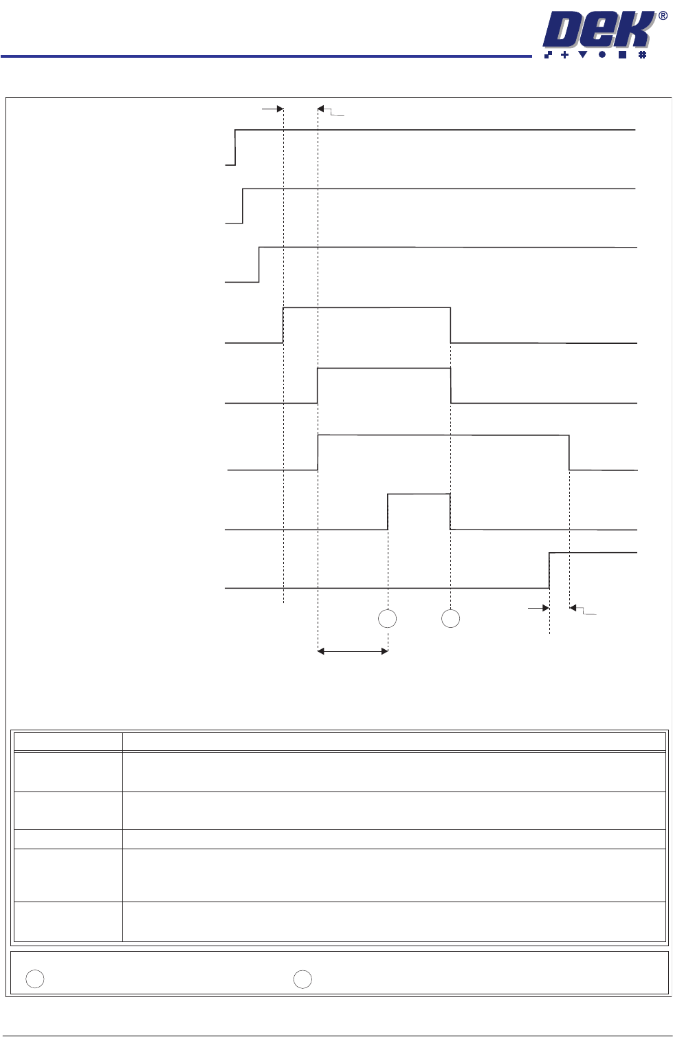
Sanyo Upline Logical Timing Diagram
Upline M/C
(I/P to DEK M/C)
Run Signal
DEK M/C
(O/P from DEK M/C)
O/P M/C
Run Signal
DEK M/C
(O/P from DEK M/C)
O/P M/C PCB
Requirement Signal
Upline M/C
(I/P to DEK M/C)
Ready Signal
Upline M/C
(I/P to DEK M/C)
PCB Transfer
Signal
DEK M/C Belts Running
DEK M/C Input Sensor
DEK M/C Board At Stop Sensor
DEK M/C
Ready
Board At Stop
Transfer Complete
< Transfer Period
Belt Overrun
< Transfer Period
Sanyo Upline Logical Timing Diagram
A
B
- Board Trailing Edge at Sensor
- Board Leading Edge at Sensor
A
B
NOTES
This signal informs the printer that the upline machine is in automatic operation. When
this signal is off, the printer stops after completing the current board.
Run Signal
OM
Run Signal
/P /C
Ready Signal
O/P M/C
PCB Requirement
Signal
PCB Transfer
Signal
This signal shows that the upline machine is transferring a board. Upon receipt of this
signal the printer starts the belts to take in the board.
This signal informs the upline machine that the printer is ready to receive a board. A
board transfer is only possible when this signal is on.
This signal shows that the upline machine is ready to start processing a board.
This signal informs the upline machine that the printer is in automatic operation, ie
initialized.
Signal Name Definition