00197975-06_UM_TX-Serie_EN.pdf - 第118页
3 Technical data and assemblie s User manual SIPLACE TX-Series 3.3 Dimensions and weight From s oftware version 713.0 Edition 01/ 2020 118 3.3.3 Center of gravity 3 Fig. 3.3 - 4 Center of gravity in millimeters Center of…
User manual SIPLACE TX-Series 3 Technical data and assemblies
From software version 713.0 Edition 01/2020 3.3 Dimensions and weight
117
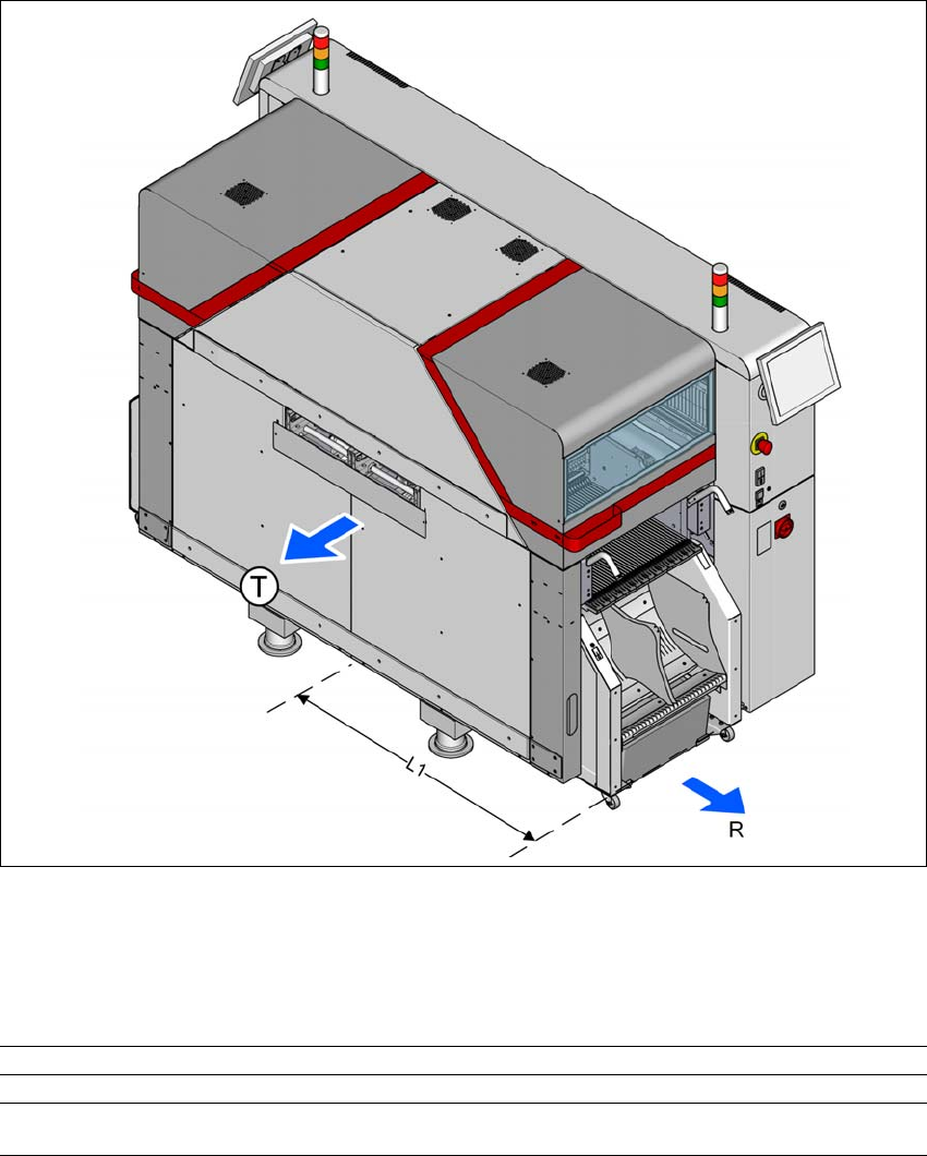
3.3.2 Maneuvering distances for component trolleys
3
Fig. 3.3 - 3 Maneuvering distances of component trolleys in SIPLACE TX placement machines
The maneuvering distance R of the component trolleys in the SIPLACE TX placement machines
is as follows:
3
Location (outside) Location (inside)
R Maneuvering distance 800 mm 680 mm
L1 Machine center to outer edge of component trol-
ley TX
1222 mm 1102 mm
3 Technical data and assemblies User manual SIPLACE TX-Series
3.3 Dimensions and weight From software version 713.0 Edition 01/2020
118
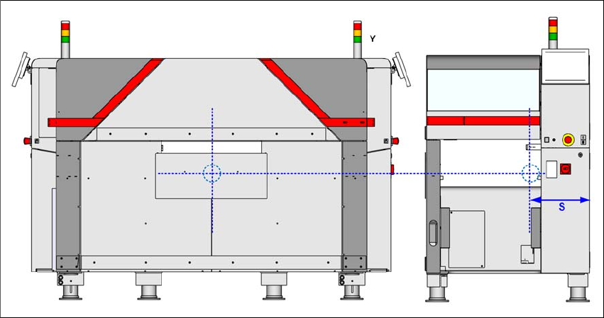
3.3.3 Center of gravity
3
Fig. 3.3 - 4 Center of gravity in millimeters
Center of gravity S = 420 mm
User manual SIPLACE TX-Series 3 Technical data and assemblies
From software version 713.0 Edition 01/2020 3.4 Overview of the modules
119
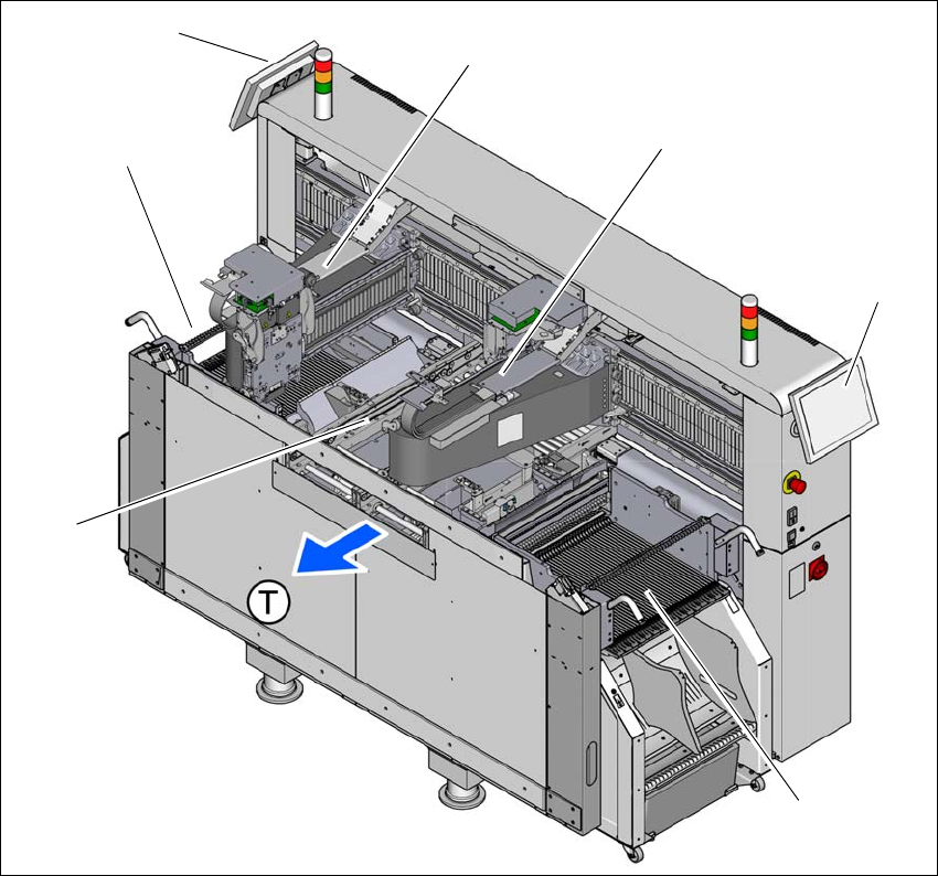
3.4 Overview of the modules
3
3
Fig. 3.4 - 1 Component overview - example of SIPLACE TX2
(1) Location 1 with component trolley, tape cutter, empty tape duct
(2) Monitor at location 1
(3) Gantry at location 1 (placement head, depending on configuration)
(4) Gantry at location 2 (placement head, depending on configuration)
(5) Monitor at location 2
(6) Location 2 with component trolley, tape cutter, empty tape duct
(7) Board conveyor
(T) Direction of PCB transport
(1)
(3)
(4)
(6)
(2)
(7)
(5)