00197975-06_UM_TX-Serie_EN.pdf - 第161页
User manual SIPLACE TX-Series 3 Technical data and assemblies From software version 713.0 Edition 01/2020 3.8 SIPLACE tape fee d er modules for SIPLACE TX-Series 161 3.8.3 Linear Dipping Unit X (LDU X) Item no. 001 1701 …

3 Technical data and assemblies User manual SIPLACE TX-Series
3.8 SIPLACE tape feeder modules for SIPLACE TX-Series From software version 713.0 Edition 01/2020
160
3.8.2.2 Technical data
3
Length 584.9 mm
Height 199.5 mm
Width 57.6 mm
Feeder module locations filled 5 tracks, each with
8 mm
Weight 4.6 kg
Diameter of smallest possible individual droplet
*a
*)a at 100 µm nozzle diameter and use of Heraeus PD 205A-Jet glue (at 53°C) or Loctite
3621 (at 53°C)
0.7 - 0.8 mm (+/- 0.1 mm)
Diameter of droplet formed from 5 shots
a
1.0 mm (+/- 0.2 mm)
Height of individual droplets
a
0.15 mm (+/- 0.02 mm)
Height of droplet formed from 5 shots
a
0.2 - 0.3 mm
User manual SIPLACE TX-Series 3 Technical data and assemblies
From software version 713.0 Edition 01/2020 3.8 SIPLACE tape feeder modules for SIPLACE TX-Series
161
3.8.3 Linear Dipping Unit X (LDU X)
Item no. 00117011-xx Linear dip module for flux / LDU-X
Item no. Dip plates see section 3.8.3.4
, page 163
3
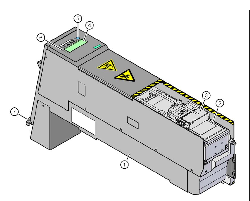
Fig. 3.8 - 4 Linear Dipping Unit (LDU X)
(1) LDU X
(2) Dip plate
(3) Flux container
(4) Display panel (4 lines each with 20 characters)
(5) Operator panel with 6 membrane keys
(6) LED for status displays
(7) EMERGENCY OFF button

3 Technical data and assemblies User manual SIPLACE TX-Series
3.8 SIPLACE tape feeder modules for SIPLACE TX-Series From software version 713.0 Edition 01/2020
162
3.8.3.1 Description
The Linear Dipping Unit X (Linear Dipping Unit X, item 1 in fig. 3.8 - 4) is used for coating Flip-
Chips and CSP components with flux. The flux container (item 3 in fig. 3.8 - 4
) slides with a linear
movement over the dip plate (item 2 in fig. 3.8 - 4
) and coats the cavity in the dip plate with a layer
of flux (predefined layer thickness). The parameters for coating a component with flux are pre-
scribed in SIPLACE Pro. The component is wetted and then the flux layer is renewed. This se-
quence guarantees consistent processing conditions for the components.
The display field (item 4 in fig. 3.8 - 4
, page 161) shows the individual menus for actions and op-
erating parameters. The buttons on the operator panel (item 5 in fig. 3.8 - 4
, page 161) allow you
to select menus, edit and save parameters. The 4 LEDs (item 6 in fig. 3.8 - 4
, page 161) on the
display field signal the status of the LDU-X. The EMERGENCY STOP button (item 7 in fig. 3.8 -
4, page 161) immediately switches the LDU-X off.
The LDU-X is taken into account as an independent feeder module type in the setup. This module
can be set up on the component trolleys of the SIPLACE TX-Series. An implemented warming
function allows the viscosity of the flux to be altered. For test purposes, the LDU-X can be oper-
ated outside the machine with the energy and data interface for X feeder modules (see section
3.8.4
, page 164).
3.8.3.2 Technical data
Further technical data and details can be found in the "SIPLACE LDU-X" user manual.
Occupied 8mm locations on the SIPLACE TX com-
ponent trolley
9
Component size Max. 55 mm x 55 mm, according to place-
ment head type
Max. 45 mm x 45 mm for TwinStar
The adjustable flux layer thickness 15 - 260 μm
Tolerance of the layer thicknesses ± 5 μm ... ± 10 µm
Time for applying the flux to the dip plate > 3s
Component dipping time adjustable using the software
Flux Indium TACFlux 010 / 013
Kester TSF-6502 / 6522
Alphametals OM338 / OM338PT
Almit BM1 RMA
Cookson WS 3018lv
etc.
Placement heads which can be used MultiStar, SpeedStar, TwinStar