00197975-06_UM_TX-Serie_EN.pdf - 第174页
3 Technical data and assemblie s User manual SIPLACE TX-Series 3.9 Component trolley From software version 713.0 Edition 01/2020 174 3.9.5 SIPLACE TX-Series t ape cont ainer 3.9.5.1 Description The tape container ca n ho…
User manual SIPLACE TX-Series 3 Technical data and assemblies
From software version 713.0 Edition 01/2020 3.9 Component trolley
173
3
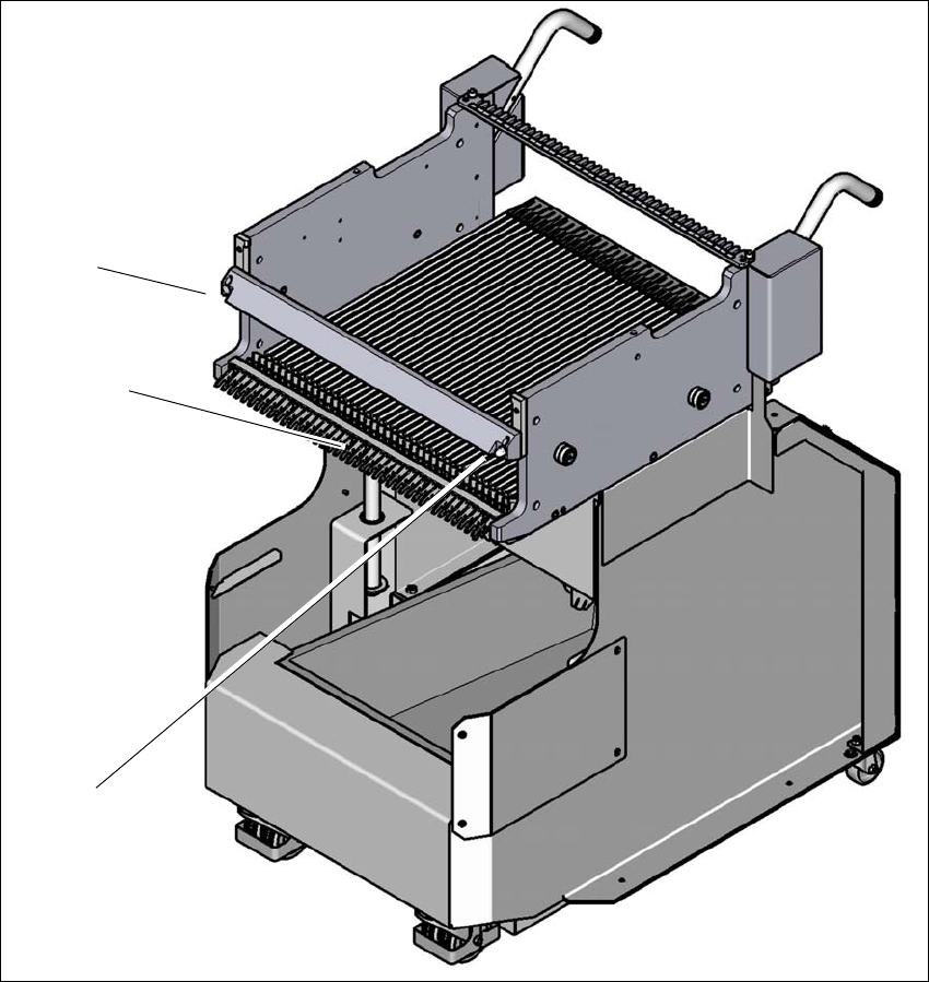
Fig. 3.9 - 5 Changeover table, SIPLACE TX-Series, front view
(1) Centering hole on the changeover table
(2) Locking latches
(3) Centering pin on the changeover table
(1)
(2)
(3)
3 Technical data and assemblies User manual SIPLACE TX-Series
3.9 Component trolley From software version 713.0 Edition 01/2020
174
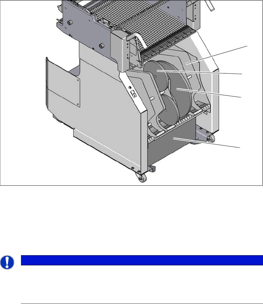
3.9.5 SIPLACE TX-Series tape container
3.9.5.1 Description
The tape container can hold reels with a diameter of 13" and 7" (option).
3
Fig. 3.9 - 6 SIPLACE TX-Series component trolley, with tape container
(1) Tape container with separating plate
(2) Tape reel 7" (optional)
(3) Tape reel 13"
(4) Waste tape container
3
PLEASE NOTE
Using spindles
TX component trolleys do not generally need spindles.
Use spindles if the error message "Timeout" appears frequently on the X feeder
module.
(3)
(2)
(4)
(1)
User manual SIPLACE TX-Series 4 Setting up and commissioning
From software version 713.0 Edition 01/2020 4.1 Safety instruction for transportation
175
4 Setting up and commissioning
4.1 Safety instruction for transportation
4
4
4
WARNING
Observe the applicable accident prevention regulations!
The applicable accident prevention regulations concerning the transportation of
heavy goods must be followed.
WARNING
Risk of injuries!
Make sure that there are no people in the hazard area.
DANGER
Risk of placement machine tilting - only transport the placement machine with shipping
braces and steel spacers fitted.
There is a risk of tilting if the required specifications for the fork-lift and the attachment
points on the placement machine are not observed!
The placement machine may only be lifted for transportation at the side on which the
output end of the placement machine is located (see section 4.4
, page 186).
Both shipping braces with steel spacers must be fitted to the placement machine
(see fig. 4.2 - 4
, page 183).
The forks of the fork-lift must be pushed between the contact surfaces of the place-
ment machine (machine frame) and the steel spacers. The steel spacers are used
as an additional safety measure to prevent the placement machine from tilting.
Only use the specified fork-lift for transportation of the placement machine. Observe
the specifications of the fork-lift (see section 4.2.5.3
, page 181).
DANGER
Risk of tilting the transportation crate or the pallet!
There is a risk of tilting if the required specifications for the fork-lift are not observed!
Make sure you only use the specified equipment for transportation. Observe the
specifications of the transportation equipment (see section 4.2.5.3
, page 181).