00197975-06_UM_TX-Serie_EN.pdf - 第179页
User manual SIPLACE TX-Series 4 Setting up and commissioning From software version 713.0 Edition 01/2020 4.2 Configuration whe n delivered 179 4.2.4 Shipping braces The SIPLACE TX has two sh ipping braces with steel spac…

4 Setting up and commissioning User manual SIPLACE TX-Series
4.2 Configuration when delivered From software version 713.0 Edition 01/2020
178
4.2 Configuration when delivered
4.2.1 Services
As a special service, SIPLACE offers to realize the complete integration of your SIPLACE place-
ment machine in your production line. With our extensive expertise and by using the right tools
and equipment, we can ensure that the installation process runs smoothly and efficiently. How-
ever, this will require you to clarify the infrastructure aspects in advance and make any necessary
changes at your production facility.
4.2.2 Shipping packaging
The SIPLACE TX is delivered together with the 2 component trolleys in a crate or on a pallet.
Within Europe, the machine and component trolleys will be shipped on a wooden pallet, packaged
in plastic film. Outside Europe, the placement machine and component trolleys are supplied in
wooden crates.
4
4.2.3 Checking a delivery
Check the delivery for damage.
Check the shock sensors at location 1.
Unpack the machine and the accessories and check the delivery for completeness (reference
delivery note).
Document the results in the installation report /acceptance protocol.
4
CAUTION
Damage from condensation
To avoid damage from condensation, only open the plastic placement machine packag-
ing once the placement machine or the components have adjusted to the ambient tem-
peratures. This can take up to 24 hours.
User manual SIPLACE TX-Series 4 Setting up and commissioning
From software version 713.0 Edition 01/2020 4.2 Configuration when delivered
179
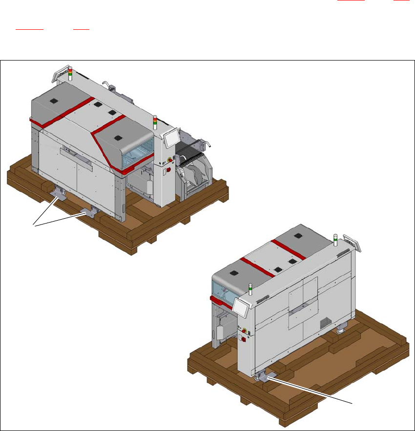
4.2.4 Shipping braces
The SIPLACE TX has two shipping braces with steel spacers (see item 1 in fig. 4.2 - 1, page 179)
screwed to the feet. In addition, a shipping brace is screwed to the opposite side (see item 2 in
fig. 4.2 - 1
, page 179). Furthermore, the placement machine is secured with wooden brackets to
prevent it slipping. The component trolley is also fixed with shipping braces.
4
Fig. 4.2 - 1 Transportation crate/pallet - shipping braces
(1) Shipping braces with steel spacers - front
(2) Shipping braces with steel spacers - back
The shipping crate or pallet with the shipping braces and steel spacers must be kept for use later
on.
1
2
4 Setting up and commissioning User manual SIPLACE TX-Series
4.2 Configuration when delivered From software version 713.0 Edition 01/2020
180
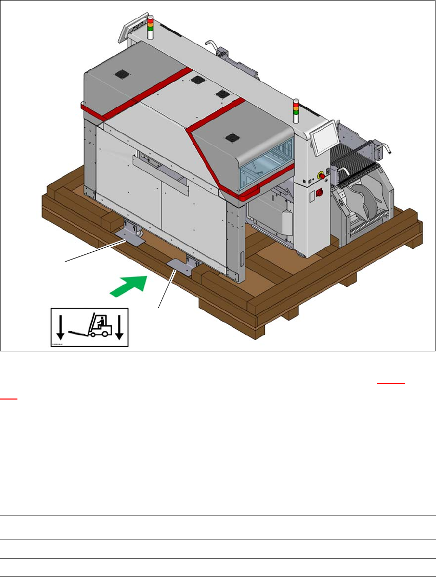
4.2.5 Transporting the placement machine in the shipping crate or on the pallet
4
Fig. 4.2 - 2 Transportation crate/pallet - attachment points for transportation with the fork-lift
The transport crate or pallet should preferably only be lifted at the side (item A in fig. 4.2 - 2, page
180
) on which the output end of the machine is located.
Transport the SIPLACE TX on the pallet or in the crate as near as possible to the final site of
use.
4.2.5.1 Shipping packaging dimensions
The dimensions of the pallets and wooden crates are listed in the following table:
4
(A)
1
1
Placement machine (L x W x H)
Pallet 2670mm x 2100mm
Wooden crate 2670 mm x 2100 mm x 1850