00197975-06_UM_TX-Serie_EN.pdf - 第182页
4 Setting up and commissioning Us er manual SIPLACE TX-Series 4.2 Configuration when delivered From software version 713.0 Edit ion 01/2020 182 4.2.6 Lif ting the p lacement machine off the p allet 4 Fig. 4.2 - 3 Contact…

User manual SIPLACE TX-Series 4 Setting up and commissioning
From software version 713.0 Edition 01/2020 4.2 Configuration when delivered
181
4.2.5.2 Weight of machine when ready for dispatch
The following table contains the weights of the placement machines prepared for dispatch, includ-
ing packaging.
4
4.2.5.3 Transportation equipment for transporting the placement machine in the packaging
Use a fork-lift truck with the following specification to carry the placement machine:
4
Placement machine Dispatch within Europe Dispatch overseas
SIPLACE TX with two component trol-
leys
2350 kg 2600 kg
Fork length Min. 1800 mm
Lifting power Min. 3000 kg
4 Setting up and commissioning User manual SIPLACE TX-Series
4.2 Configuration when delivered From software version 713.0 Edition 01/2020
182
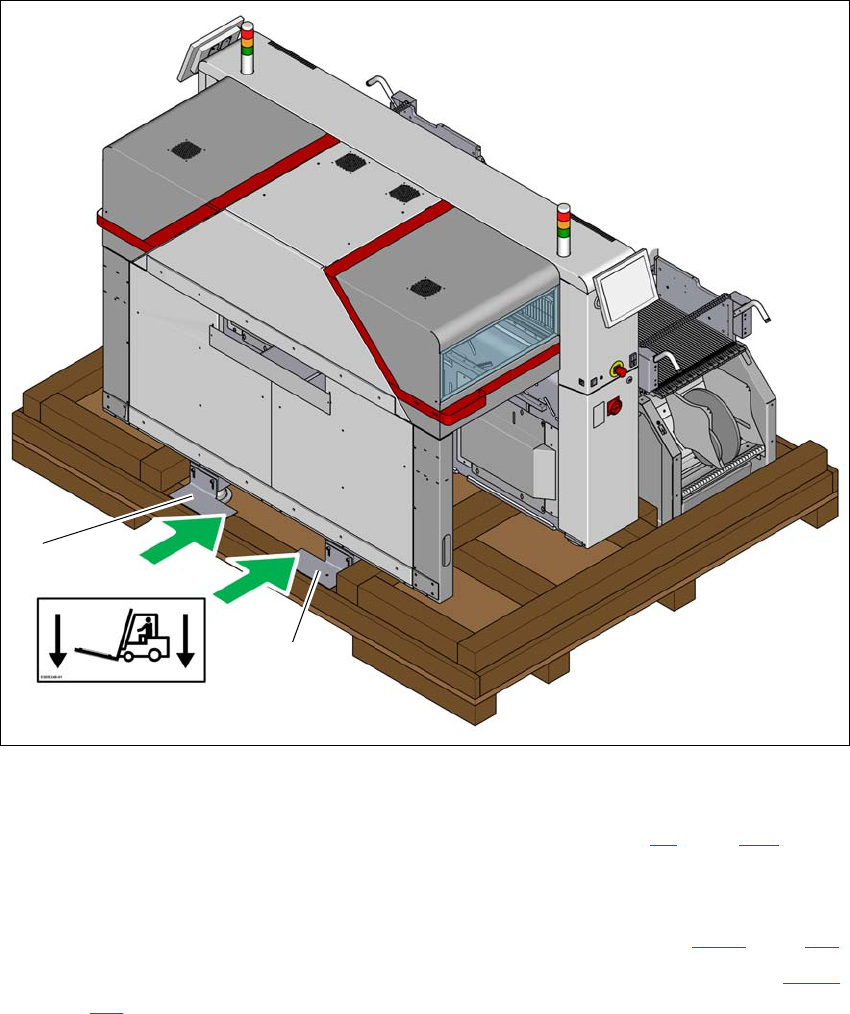
4.2.6 Lifting the placement machine off the pallet
4
Fig. 4.2 - 3 Contact points for transportation with the fork-lift
(1) Shipping braces with steel spacer
During transportation, always follow the safety instructions in section 4.1, page 175).
Loosen the two shipping braces (1) from the base of the crate or from the pallet. The two
braces and the steel spacers remain fitted to the placement machine.
Loosen and remove the shipping braces on the opposite side (item 2 in fig. 4.2 - 1, page 179).
The placement machine may ONLY be lifted with a fork-lift on the side (item A in fig. 4.2 - 3,
page 182
) on which the output end of the machine is located.
Position the fork-lift at cross-angles to the direction of conveyor transport (at the output end).
Open the forks until the forks are between the two placement machine feet and the contact
surfaces of the placement machine lie evenly on the forks.
(A)
1
1
User manual SIPLACE TX-Series 4 Setting up and commissioning
From software version 713.0 Edition 01/2020 4.2 Configuration when delivered
183
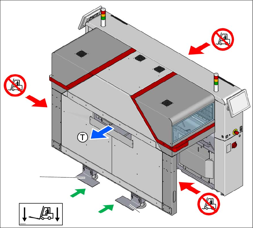
Push the forks between the contact surfaces of the placement machine (machine frame) and
the steel spacers. The steel spacers are used as an additional safety measure to prevent the
placement machine from tilting.
Push the forks fully under the placement machine, so that these are positioned properly on
the machine frame of the opposite side.
4
Fig. 4.2 - 4 Contact surfaces - Forks parallel to the direction of PCB transport on the output side
(T) Direction of travel for PCB conveyor
(1) Fork-lift forks between the machine feet
(2) Never lift the placement machine at the input side! Risk of tilting!
(3) Never lift the placement machine at the component trolley locations with a fork-lift! Risk of tilt-
ing!
(4) Shipping braces with steel spacer
Position the fork-lift at cross-angles to the direction of conveyor transport (at the output end).
Open the forks until the forks are between the two placement machine feet and the contact
surfaces of the placement machine lie evenly on the forks.
(2)
(1)
(3)
(3)
(4)
(4)