00197975-06_UM_TX-Serie_EN.pdf - 第197页
User manual SIPLACE TX-Series 4 Setting up and commissioning From software version 713.0 Edition 01/2020 4.4 Infrastructure at the installation location 197 F9 Gant ry 2 6,3 24 F10 Internal 6,3 24 F1 1 CSB sig nal 6,3 24…
4 Setting up and commissioning User manual SIPLACE TX-Series
4.4 Infrastructure at the installation location From software version 713.0 Edition 01/2020
196
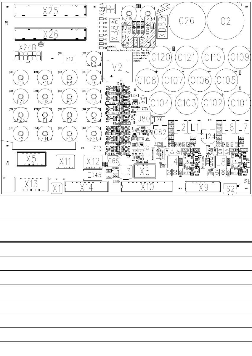
4.4.4 Overview of the microfuses
4
Fig. 4.4 - 6 Overview of the microfuses
4
Fuse Components Electricity
[A]
Voltage [V]
F1 MGCU1 6,3 24
F2 MGCU2 6,3 24
F3 Service 6,3 24
F4 Distributor 6,3 24
F5 Station PC 6,3 24
F6 PC option 6,3 24
F7 Conveyor control 6,3 24
F8 Gantry 1 6,3 24

User manual SIPLACE TX-Series 4 Setting up and commissioning
From software version 713.0 Edition 01/2020 4.4 Infrastructure at the installation location
197
F9 Gantry 2 6,3 24
F10 Internal 6,3 24
F11 CSB signal 6,3 24
F12 CSB supply 6,3 24
F13 -- -- --
F14 Head 1 6,3 42
F15 Head 2 6,3 42
F16 Conveyor drives 10,0 42
F19 Gantry 1 6,3 160
F20 Gantry 2 6,3 160
F21 Vision 6,3 42
F22 FCU 1 10 27
F23 FCU 2 10 27
Fuse Components Electricity
[A]
Voltage [V]
4 Setting up and commissioning User manual SIPLACE TX-Series
4.5 Setting up the placement machine From software version 713.0 Edition 01/2020
198
4.5 Setting up the placement machine
4.5.1 Fitting attached parts
The placement machine is delivered with the monitor and indicator lamp dismantled. To fit the in-
dicator lamps and the monitors, proceed as follows.
4.5.1.1 Fitting the indicator lamp
Insert the indicator lamp into the hole until the lamp tube projects sufficiently into the terminal
beneath.
Pull the connector slightly out of the lamp base.
Plug the connector into the bottom of the upper section of the lamp.
Turn the signaling lamp, until it engages.
4.5.1.2 Fixing the monitors
Use the fastening screws to fix the monitor to the monitor mount and then connect the cable.
Check the cable connections.
Fasten the monitor cable to the monitor with a strain relief.