00197975-06_UM_TX-Serie_EN.pdf - 第210页
4 Setting up and commissioning Us er manual SIPLACE TX-Series 4.5 Setting up the placement mac hine From software version 713.0 Edition 01/2020 210 4 4 Loosen the three other machine fe et (2) in the same way . Use t…
User manual SIPLACE TX-Series 4 Setting up and commissioning
From software version 713.0 Edition 01/2020 4.5 Setting up the placement machine
209
4.5.7 Setting the conveyor height
The placement machine stands on four machine feet.
4
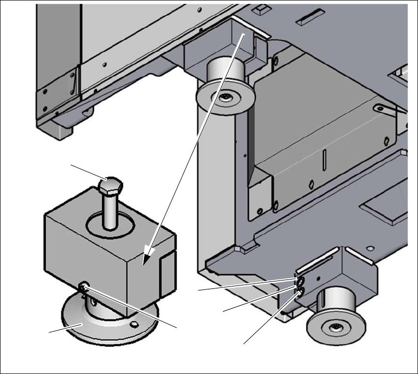
Fig. 4.5 - 5 Setting the PCB conveyor height
(1) Setting screw for height adjustment
(2) Machine foot
(3) Locking screws for machine foot
(4) Two clamping screws
(5) Threaded hole between the two clamping screws (to spread open the clamp)
Loosen the locking screw (3). The locking screw prevents falling down right after the clamp
has been loosened.
Loosen the two clamping screws (4), using the attachable ratchet and the hexagonal screw-
driver bit, size 14.
(1)
(4)
(3)
(2)
(5)
(4)

4 Setting up and commissioning User manual SIPLACE TX-Series
4.5 Setting up the placement machine From software version 713.0 Edition 01/2020
210
4
4
Loosen the three other machine feet (2) in the same way.
Use the 18 mm open-end wrench, to change the height of the machine feet (2) with the setting
screw (1), in order to reach the relevant conveyor height.
4
Adjust the placement machine (see section 4.5.7.1, page 211).
WARNING
Only loosen the clamping screws with the attachable ratchet
The clamping screws may not be loosened using the torque wrench. There is a risk of
causing injuries.
To loosen the clamping screws, only use the attachable ratchet with the appropriate
extension.
WARNING
Perform work only with the bump cap and protective gloves.
There is a risk of causing injuries to the head and hands.
Only perform work with the bump cap and protective gloves.
PLEASE NOTE
Position of setting screws for height adjustment
On the output side, the setting screws are next to the component inserts.
On the input side, the setting screws are concealed, under the power supply unit. If the
optional vacuum pump is fitted, the other setting screw is hidden by the vacuum pump
and is located below this.
User manual SIPLACE TX-Series 4 Setting up and commissioning
From software version 713.0 Edition 01/2020 4.5 Setting up the placement machine
211
4.5.7.1 Adjusting the placement machine
4
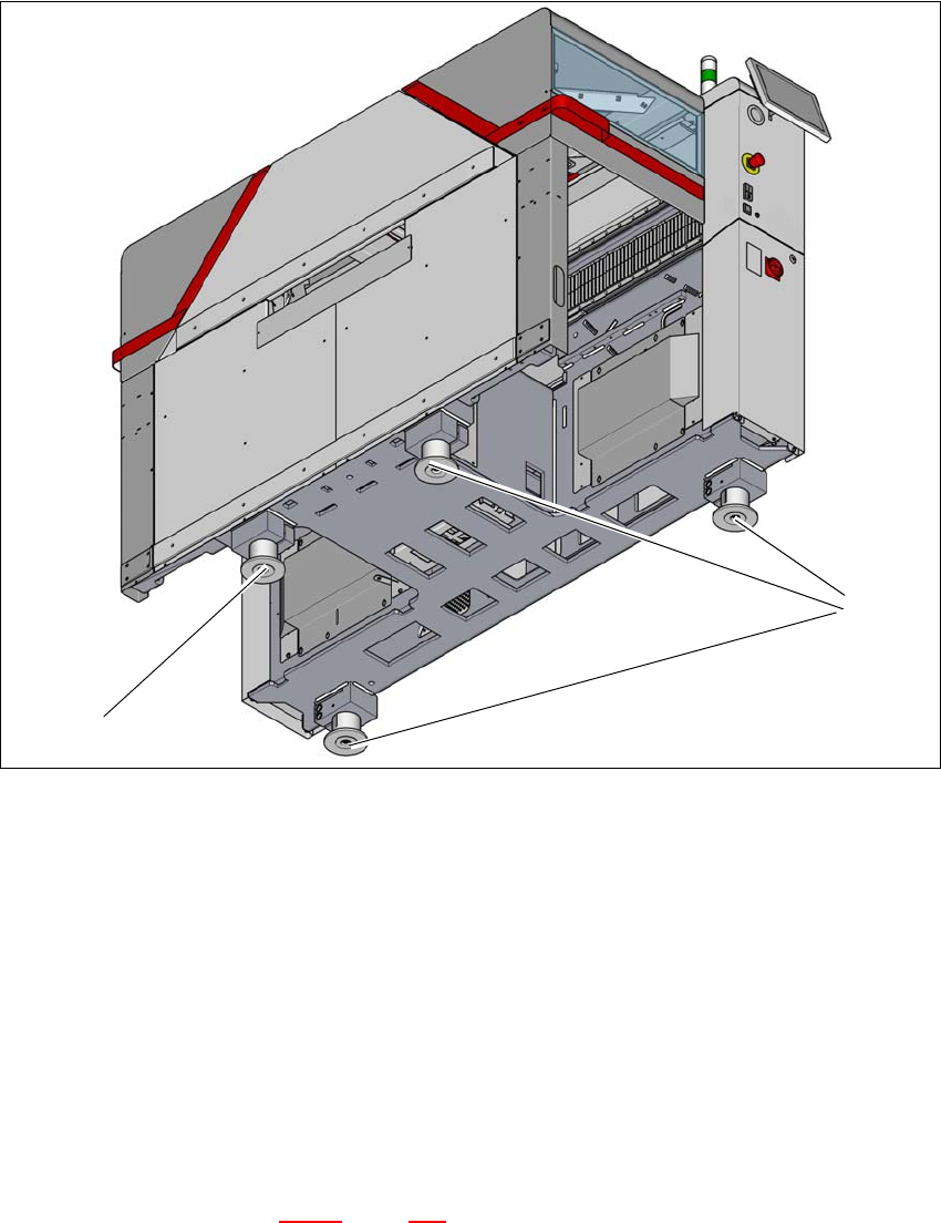
Fig. 4.5 - 6 Adjusting the placement machine
Place the placement machine spirit level (measuring accuracy of 0.02 mm) on the unclamped
lifting table and measure in the X and Y directions.
Align the placement machine in the X and Y direction, using the machine spirit level, at the
three machine feet (1). The maximum permissible deviation is 0.10 mm/m.
Then fix the fourth machine foot (2) so that it is firmly on the ground.
Check the load-bearing strength of the 4 machine feet. The 4 machine feet must touch the
ground and be evenly loaded.
The setting screws for adjusting the height of the placement machine feet must be positioned
in a load-bearing state, once the placement machine has been aligned.
Use the torque wrench to tighten the clamping screws (torque of 130 Nm) for the four machine
feet. (See also diagram 4.5 - 5
, page 209)
Hit the feet with a hammer to check the load-bearing strength of the machine feet.
Use the spirit level to check that the placement machine is accurately aligned.
(2)
(1)