00197975-06_UM_TX-Serie_EN.pdf - 第22页
1 Introduction User manual SIPLACE TX-Series 1.3 SIPLACE TX From software version 713.0 Edition 01/2020 22 1.3 SIPLACE TX The SIPLACE TX placement machine s demonstrate top quality durin g high-volume pr oduction. – Rapi…
User manual SIPLACE TX-Series 1 Introduction
From software version 713.0 Edition 01/2020 1.2 Overview
21
1
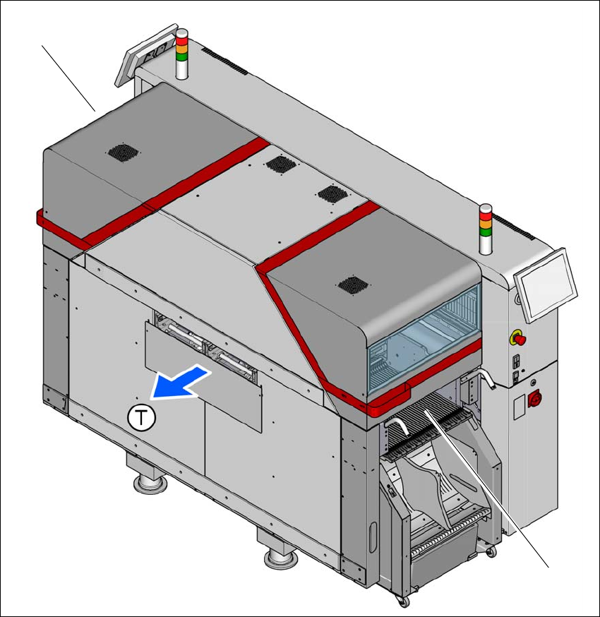
Fig. 1.2 - 2 SIPLACE TX-Series placement machine - location 2 inside
(T) Direction of travel
(1) Location 1
(2) Location 2
(1)
(2)
1 Introduction User manual SIPLACE TX-Series
1.3 SIPLACE TX From software version 713.0 Edition 01/2020
22
1.3 SIPLACE TX
The SIPLACE TX placement machines demonstrate top quality during high-volume production.
– Rapid placement at top quality,
– Very high productivity per area
– Very high accuracy
– Limitless scalability
Three placement methods are possible for processing the components:
– Collect&Place,
– Pick&Place and
– A combination of Collect&Place and Pick&Place (mixed mode).
These can be quickly and accurately positioned by linear motors, moving independently of one
another in the X and Y directions.
1.3.1 Description
–SIPLACE TX1
– Placement machine with one gantry
– Table position "outside" at location 1
– Table position "inside" at location 2
–SIPLACE TX2
– Placement machine with two gantries
– Table position "outside" at location 1
– Table position "inside" at location 2
–SIPLACE TX2i
– Placement machine with two gantries
– Table position "inside" at location 1 and 2
–SIPLACE TX2i W
– Placement machine with two gantries
– Table position "inside" at location 1 and 2
– Board width up to 280 mm
The SIPLACE TX placement machines have one placement area and a dual conveyor. Two
boards can be placed at the same time on dual conveyors.
There are two locations available for supplying components. These can be fitted with component
trolleys and configured with up to 40 tracks.

User manual SIPLACE TX-Series 1 Introduction
From software version 713.0 Edition 01/2020 1.3 SIPLACE TX
23
1.3.2 Placement Head Configurations
1
Placement
machine
Placement head Standard cameras Options
SIPLACE
TX1
C&P20 P Component camera, type
23
– Component camera, type 41
CPP_H Component camera, type
30
–None
TH Component camera, type
33
– Stationary camera, type 25
(only at location 1)
SIPLACE
TX2
C&P20P / C&P20 P Component camera, type
23
– Component camera, type 41
CPP_L/CPP_L
Component camera, type
30
– Component camera, type 45
CPP_H / CPP_H
Component camera, type
30
– Stationary camera, type 33
(only at location 1)
TH / CPP_H
Stationary camera, type 33
(only at location 1)
– Stationary camera, type 25
(only at location 1)
SIPLACE
TX2i
C&P20P / C&P20 P Component camera, type
23
– Component camera, type 41
CPP_L / C&P20P
*a
Component camera, type
23
Component camera, type
30
– Component camera, type 41
– Component camera, type 45
CPP_L/CPP_L
Component camera, type
30
– Component camera, type 45
CPP_H / CPP_H
Component camera, type
30
– Component camera, type 45