00197975-06_UM_TX-Serie_EN.pdf - 第231页
User manual SIPLACE TX-Series 5 Tasks at the placement machine From software version 713.0 Edition 01/2020 5.3 Switching on the SIPLACE line 231 5.3.4 st art button action The action performe d by the st art button can b…
5 Tasks at the placement machine User manual SIPLACE TX-Series
5.3 Switching on the SIPLACE line From software version 713.0 Edition 01/2020
230
5
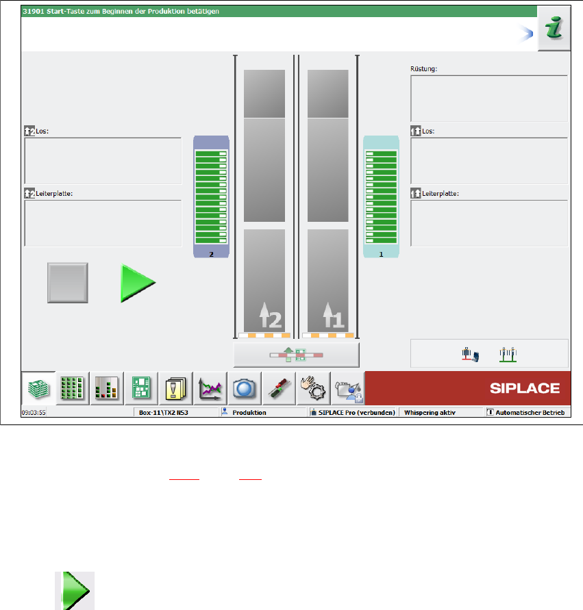
Fig. 5.3 - 1 "Production" view after loading the station software (example)
The status field (see section 5.5.1, page 235) shows the current status of the station and the action
to be performed.
Press the start button when you see the request "Press Start button".
A reference run will be performed. After completion of this reference run, the station is ready
for operation.
The icon will be shown in the working area of the user interface (enabled).
User manual SIPLACE TX-Series 5 Tasks at the placement machine
From software version 713.0 Edition 01/2020 5.3 Switching on the SIPLACE line
231
5.3.4 start button action
The action performed by the start button can be set.
Open the "Check sensors and functions" view (see section 5.5.3, page 236).
The following settings are possible:
Start production automatically 5
Standard setting.
Pressing the start button automatically begins the production process.
Do not change production status 5
This is used, for example, to calibrate and test the placement machine
Pressing the start button simply closes the control circuit; production is not started immediately.
5
5.3.5 "Switching on the SIPLACE line" flow chart
The following flow diagram shows the actions performed after the SIPLACE line has been
switched on.
CAUTION
Placement machine functions can be directly started via the GUI, irrespective of the start
button setting. Once the control system has been switched on, you no longer need to
press the start button on the placement machine.
5 Tasks at the placement machine User manual SIPLACE TX-Series
5.3 Switching on the SIPLACE line From software version 713.0 Edition 01/2020
232
5
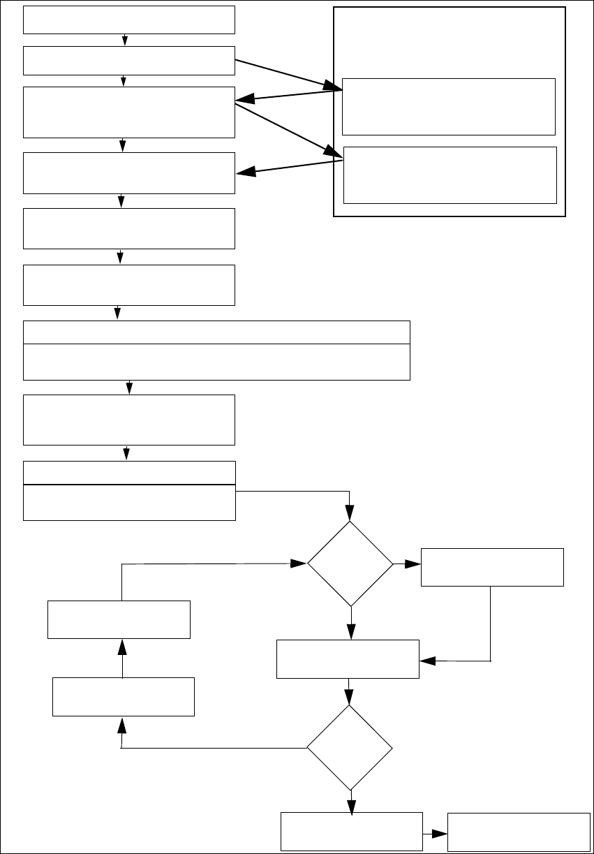
Fig. 5.3 - 2 Flow chart - switching on the "SIPLACE line"
Station computer
Switch on
Check setup
(configure feeder modules
Teach fiducials
Load board data
Press start button
Wait for reference run
Move board in
Wait for PCB
Check setup
(if table marked red
If required: change nozzle configuration
Nozzle check
Fiducials
OK?
Track error
Placement
Check setup
Fill up tracks
Placement
PCB in output conveyor
Italics: Performed or reported by the station
Yes
Yes
No
No
Presettings on the
placement ma-
chine
Download assistant
Programming system
Tasks
Confirm conversion in download
assistant
Bold lettering: job to be performed by op-
erator