00197975-06_UM_TX-Serie_EN.pdf - 第238页
5 Tasks at the placement machi ne User manual SIPLACE TX-Series 5.5 The user interface From software version 713.0 Edition 01/202 0 238 5 Fig. 5.5 - 3 User interface in the "Feeder mo d ule, components and nozzles&q…
User manual SIPLACE TX-Series 5 Tasks at the placement machine
From software version 713.0 Edition 01/2020 5.5 The user interface
237
5.5.4 Operating the station software in the views
Most views which can be accessed via the toolbar (see section 5.5.3, page 236) have an addi-
tional vertical toolbar with subviews and functions, on the right-hand side of the user interface.
5
Example: View: "Feeder modules, components and nozzles"
Click on "Feeder modules, components and nozzles" in the toolbar.
The following view will open:
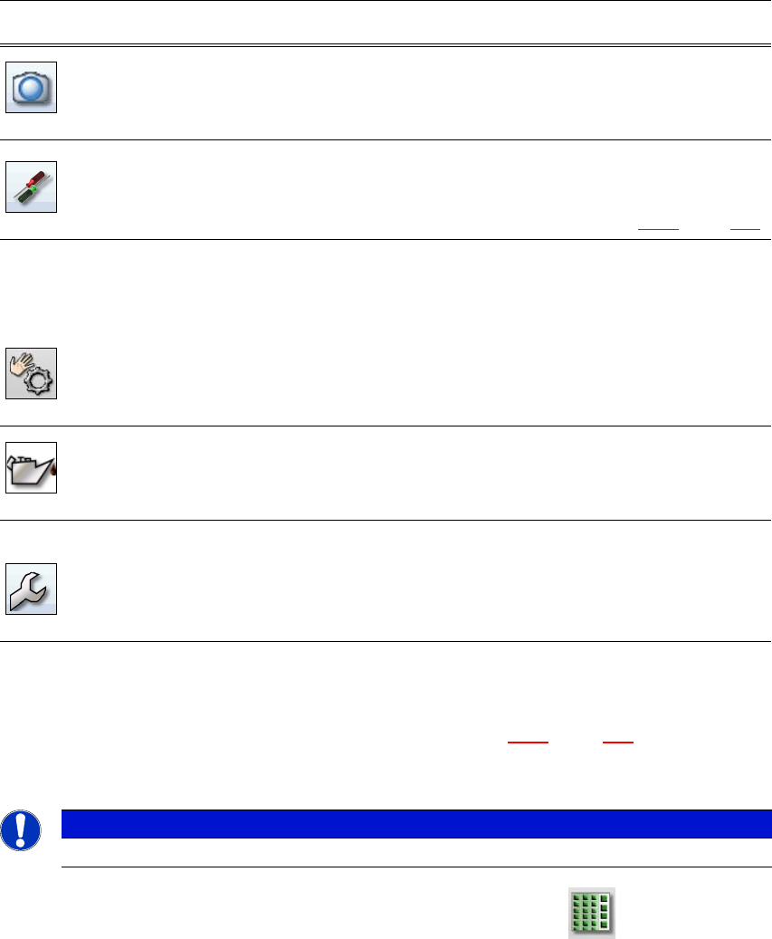
Live image during
placement
Shows the individual live camera images.
Only available from operator level "Advanced Production" :
Allows you to view and save the Vision dump.
Settings Contains all the settings and options.
Allows you to set the operator level and the user interface language.
Allows you to display and edit the settings, user settings, placement
machine options and software options, see section 5.5.5
, page 240.
Check sensors
and functions
Contains information and functions for tests and diagnoses.
Allows you to set the function of the start button for the placement
machine.
Only available from operator level "Advanced Production" :
Allows you to test the complete reference run and C&P20 head
functions.
Single functions and continuous runs. Each gantry is addressed
individually.
Maintenance sta-
tus
Contains information about the maintenance status for the place-
ment machine.
For more information, read the maintenance manual.
Service Service tools.
Only available from operator level "Service (customer)".
Allows you to set up and calibrate the SIPLACE placement ma-
chines, download embedded software versions, calibrate and con-
figure the entire placement machine.
Icon View Description
PLEASE NOTE
For a detailed description of the individual functions refer to the Online Help.
5 Tasks at the placement machine User manual SIPLACE TX-Series
5.5 The user interface From software version 713.0 Edition 01/2020
238
5
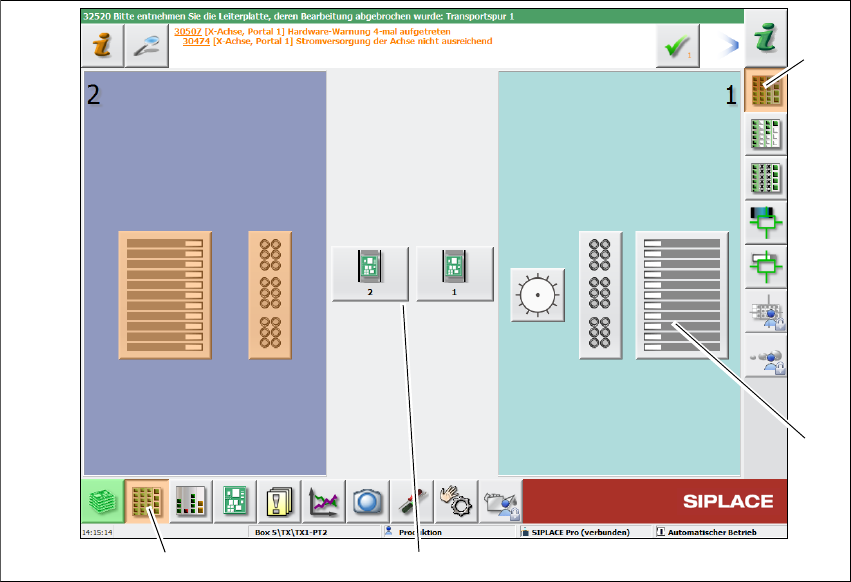
Fig. 5.5 - 3 User interface in the "Feeder module, components and nozzles" view (example)
Legend
(1) Toolbar ("Feeder modules, components and nozzles" button)
(2) Vertical toolbar in "Feeder modules, components and nozzles" view
(3) Button for both conveyor lanes
(4) Button for table at location 1
Click, for example, on the table at location 1 (button 4), to check the configuration.
(1)
(2)
(3)
(4)
User manual SIPLACE TX-Series 5 Tasks at the placement machine
From software version 713.0 Edition 01/2020 5.5 The user interface
239
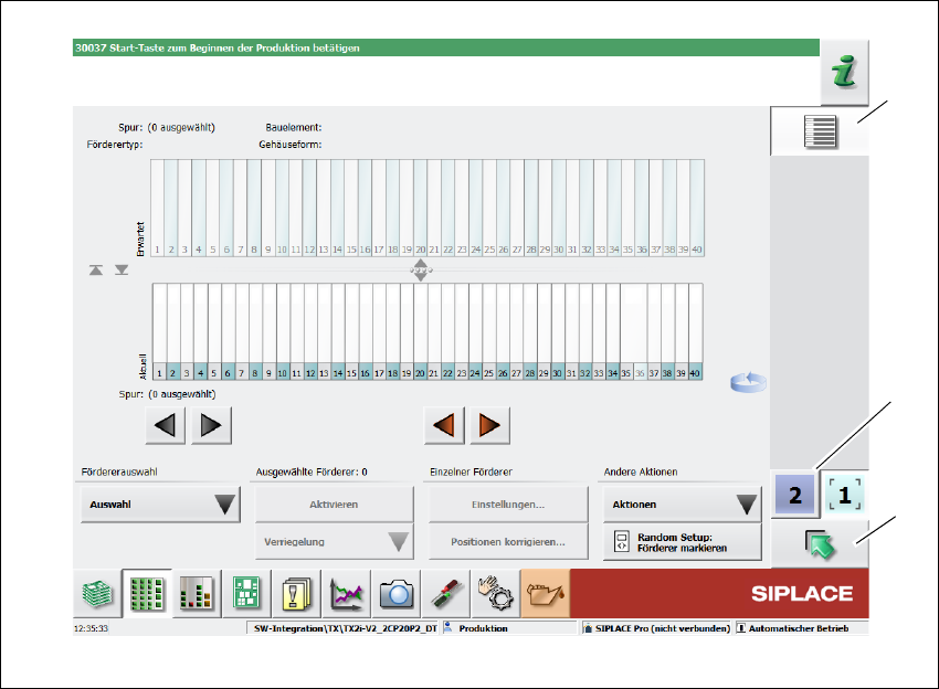
The following view will open:
5
Fig. 5.5 - 4 User interface in the "Tables" view (example)
Legend
(1) Vertical toolbar "Tables"
(2) "Up one level" button, to return to previous view (here: "Feeder modules, components and
nozzles" view, see previous diagram)
(3) Buttons for changing directly to a different gantry
(1)
(2)
(3)