00197975-06_UM_TX-Serie_EN.pdf - 第241页
User manual SIPLACE TX-Series 5 Tasks at the placement machine From software version 713.0 Edition 01/2020 5.5 The user interfac e 241 5.5.6 Application-oriented opera tion via color-coding markings Icons, buttons and vi…
5 Tasks at the placement machine User manual SIPLACE TX-Series
5.5 The user interface From software version 713.0 Edition 01/2020
240
5.5.5 Settings
The "Settings" view allows you to change the various user settings, software options and place-
ment machine options.
Click on "Settings" in the toolbar .
The right-hand side shows an additional toolbar. The following table briefly describes the icons
and settings.
5
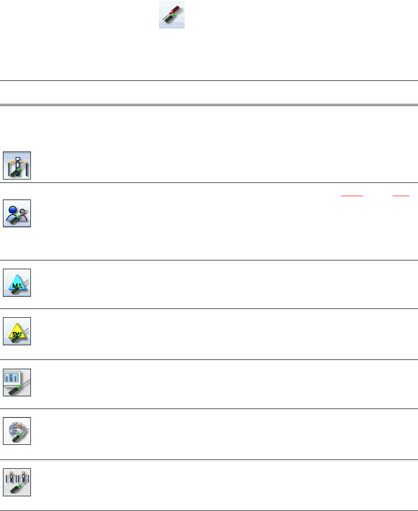
Icon Settings Description
Machine settings Only for "Advanced production", "Service customer" or "Service
SIPLACE".
Allows you to set the operating mode and options (e.g. running
options).
Shutting down the placement machine
Allows you to change over to the operating system.
User settings Allows you to set the operator level (see section 5.3.3
, page 229).
Allows you to set the language. As a default, English, German or
Chinese can be selected. ASM provides additional languages as a
download.
Further options can be set from the "Advanced production" operator
level.
Machine options No options can be changed in the "Production" level.
Configuration of the placement machine options.
Software options Only for "Advanced production", "Service customer" or "Service
SIPLACE".
Allows you to activate various test functions.
GUI settings Allows you to check and define GUI settings.
Overview of con-
nected external
systems
Shows all connected external systems (e.g. OIS, SetupCenter).
Shows the connection status and the memory used or deletes the
connected systems.
Adjacent place-
ment machine
Shows the adjacent placement machine.

User manual SIPLACE TX-Series 5 Tasks at the placement machine
From software version 713.0 Edition 01/2020 5.5 The user interface
241
5.5.6 Application-oriented operation via color-coding markings
Icons, buttons and views can be highlighted in color. These color-coded highlights give you a clear
overview of when operator action is required or when warnings have been issued.
The station software uses the following color coded highlights:
5
Color State Meaning
Red Alert Operator action required.
Only available in the "Feeder module, components and noz-
zles" view.
Orange Warning Operator notification is present.
Immediate operator action is not required.
Only available in the "Feeder module, components and noz-
zles" view.
Green In progress Icon or button has placement machine under control and the
state is OK.
Only available in the "Production", "Feeder modules, compo-
nents and nozzles", "Boards", "Check sensors and functions"
and "Service" views.
5 Tasks at the placement machine User manual SIPLACE TX-Series
5.6 Alert information and online help From software version 713.0 Edition 01/2020
242
5.6 Alert information and online help
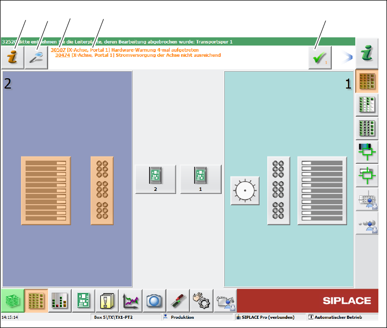
If alerts occur during placement machine operations, the alert message in the status field of the
user interface will be shown in red. The icon for alert information will be active.
The button highlighted in red in the toolbar indicates that operator action is required.
5
Fig. 5.6 - 1 View with alarm notification (example)
Legend for fig. 5.6 - 1
(1) "Alert information" icon: for opening the help function for the current alert
(2) "Details" icon: for opening detailed information (e.g. error source, time of occurrence)
(3) Alert number
(4) Alert message: brief information about the alert
(5) "Acknowledge alert" icon: for deleting the alert display
(1)
(2) (3)
(4)
(5)