00197975-06_UM_TX-Serie_EN.pdf - 第258页
5 Tasks at the placement machi ne User manual SIPLACE TX-Series 5.10 Setting up the feeder modules From software version 713.0 Ed ition 01/2020 258 5.10.3 Using the X feeder module 5.10.3.1 Check the X feeder module befo…

User manual SIPLACE TX-Series 5 Tasks at the placement machine
From software version 713.0 Edition 01/2020 5.10 Setting up the feeder modules
257
On standby, the status display (item 2 in fig. 5.10 - 1, page 256) lights up green if the X axis feeder
module is contained in the current setup. If the feeder module is not contained in the current setup,
the status display remains off.
The feeder module is locked in position in the changeover table by a latch, and cannot be pulled
out. The procedure for removing feeder modules from the changeover table is as follows:
Press the removal handle (item 1 in fig. 5.10 - 1, page 256). The removal handle jumps out
and the status display goes out.
Wait approximately 1 second until the lock (item 4 in fig. 5.10 - 1, page 256) releases the
feeder module.
Use the removal handle to pull the feeder module out of the changeover table. If you wait lon-
ger than 5 seconds, the feeder module will be locked once more. The status display will shine
red.
Engage the removal handle once more. If the feeder module is contained in the current setup,
the status display lights up green and the track number and increment will appear on the LCD
display once more.
5 Tasks at the placement machine User manual SIPLACE TX-Series
5.10 Setting up the feeder modules From software version 713.0 Edition 01/2020
258
5.10.3 Using the X feeder module
5.10.3.1 Check the X feeder module before using it
Check the following points before you use a feeder module on the changeover table:
The feeder module must be in perfect condition.
Tap the cover foil rocker (item 2 in fig. 5.10 - 2, page 259) lightly to make sure that it has not
jammed.
Check that the area around the pickup window (item 3 in fig. 5.10 - 2, page 259) is free
from loose components.
5
5
Press the lever (item 4 in fig. 5.10 - 2, page 259) forward slightly to open the pickup window
(item 3 in fig. 5.10 - 2
, page 259). This will raise the pick-up window slightly.
5
Remove any loose components from beneath the pick-up window.
Close the pickup window (item 3 in fig. 5.10 - 2), by returning the lever (item 4 in fig. 5.10 - 2)
to its original position.
Remove loose components from the changeover table with a brush or use a vacuum cleaner
with appropriate nozzle.
5
PLEASE NOTE
Empty the component disposal compartment (item 5 in fig.5.10 - 2, page 259), be-
fore you
shake components out of the feeder module.
PLEASE NOTE
The tensioned cover foil continues to transport the tape when the tape has been inserted
and exposes the components.
Do not press the lever (item 4 in fig. 5.10 - 2, page 259) if a tape is inserted.
PLEASE NOTE
If the component tape is already inserted, cut it off flush with the front edge of the
feeder module. There should still be 2 holes visible in the perforation.
User manual SIPLACE TX-Series 5 Tasks at the placement machine
From software version 713.0 Edition 01/2020 5.10 Setting up the feeder modules
259
If the removal handle (item 1) is still protruding, then latch it in place.
5
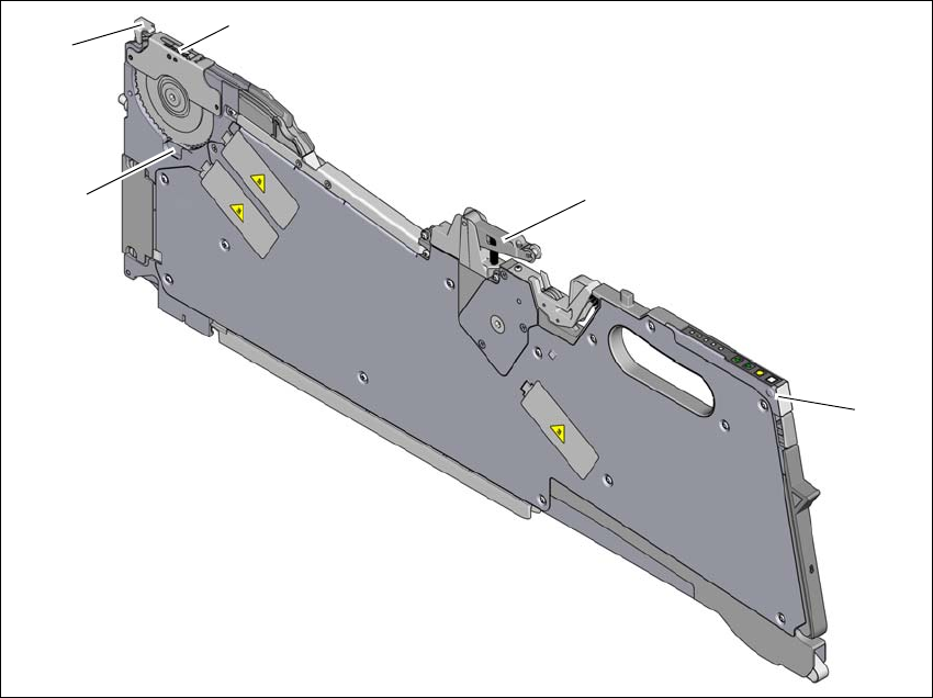
Fig. 5.10 - 2 Check the X feeder module before using it
(1) Removal handle
(2) Cover foil rocker
(3) Pickup window
(4) Lever for raising and latching the pick-up window
(5) Component disposal compartment
(1)
(2)
(3)
(4)
(5)