00197975-06_UM_TX-Serie_EN.pdf - 第82页
2 Operational safety User manual SIPLACE TX-Series 2.5 Safety features From software version 713.0 Edition 01/2020 82 2.5.2 Switches and buttons 2.5.2.1 Positions of switches and buttons 2 Fig. 2.5 - 2 Position of switch…

User manual SIPLACE TX-Series 2 Operational safety
From software version 713.0 Edition 01/2020 2.5 Safety features
81
Function 2
If the protective cover is swung upwards (45° or 60° position), the power supply to the gantry axes
will be immediately interrupted. The gantry axes stop moving. The message "Close cover" is dis-
played on the screen.
Close the protective covers and press the START button (item 2 in fig. 2.5 - 2), to continue
placement.
2 Operational safety User manual SIPLACE TX-Series
2.5 Safety features From software version 713.0 Edition 01/2020
82
2.5.2 Switches and buttons
2.5.2.1 Positions of switches and buttons
2
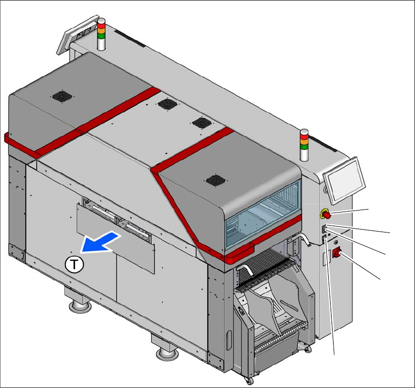
Fig. 2.5 - 2 Position of switches and buttons - PCB output end (location 2)
(1) EMERGENCY STOP button
(2) Start button (white)
(3) Stop button (black)
(4) Main switch
(5) Button for docking and undocking the component trolley at the respective location
(T) PCB transport direction
(3)
(1)
(4)
(2)
(5)
User manual SIPLACE TX-Series 2 Operational safety
From software version 713.0 Edition 01/2020 2.5 Safety features
83
2
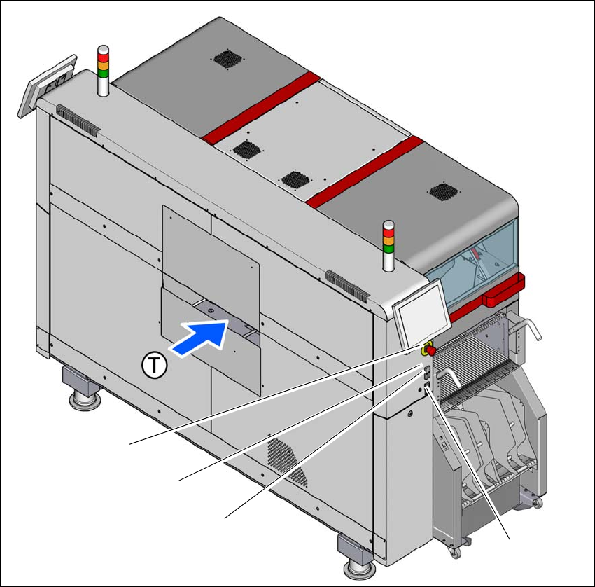
Fig. 2.5 - 3 Position of switches and buttons - PCB input end (location 1)
(1) EMERGENCY STOP button
(2) Start button (white)
(3) Stop button (black)
(4) Button for docking and undocking the component trolley at the respective location
(T) PCB transport direction
(3)
(1)
(4)
(2)