00192809-01 - 第22页
2 Safety User M anual V 1.15 - P roductivity Lift 2.5 T ransport an d assembly locks Software version V 40.1 1 Edition 01/2001 14 2. Befor e carr ying out a ny work tha t is r equired at eith er of the two lift units, th…
User Manual V 1.15 - Productivity Lift 2 Safety
Software version V 40.11 Edition 01/2001 2.5 Transport and assembly locks
13
7UDQVSRUWDQGDVVHPEO\ORFNV
'LVFRQQHFWLQJFRPSUHVVHGDLUVXSSO\
:$51,1*
Do not loosen a compressed air line without making sure that the corresponding air service unit
is pressureless by opening the hand slide discharge valve or alternatively by closing the main
valve of the compressed air supply.
/RFNLQJWKHOLIWEHOW
:$51,1*
The installation aid shown in the figures serves to lock the lift during servicing, maintenance work,
for example, when changing the toothed belt, and during transport. Any activity that involves a per-
son having to intervene in the lift area in any way should result in the following locking measures
being taken as described below. After the activities are finished and before the device is turned
on again all securities have to be removed and to be deposed at the right place.
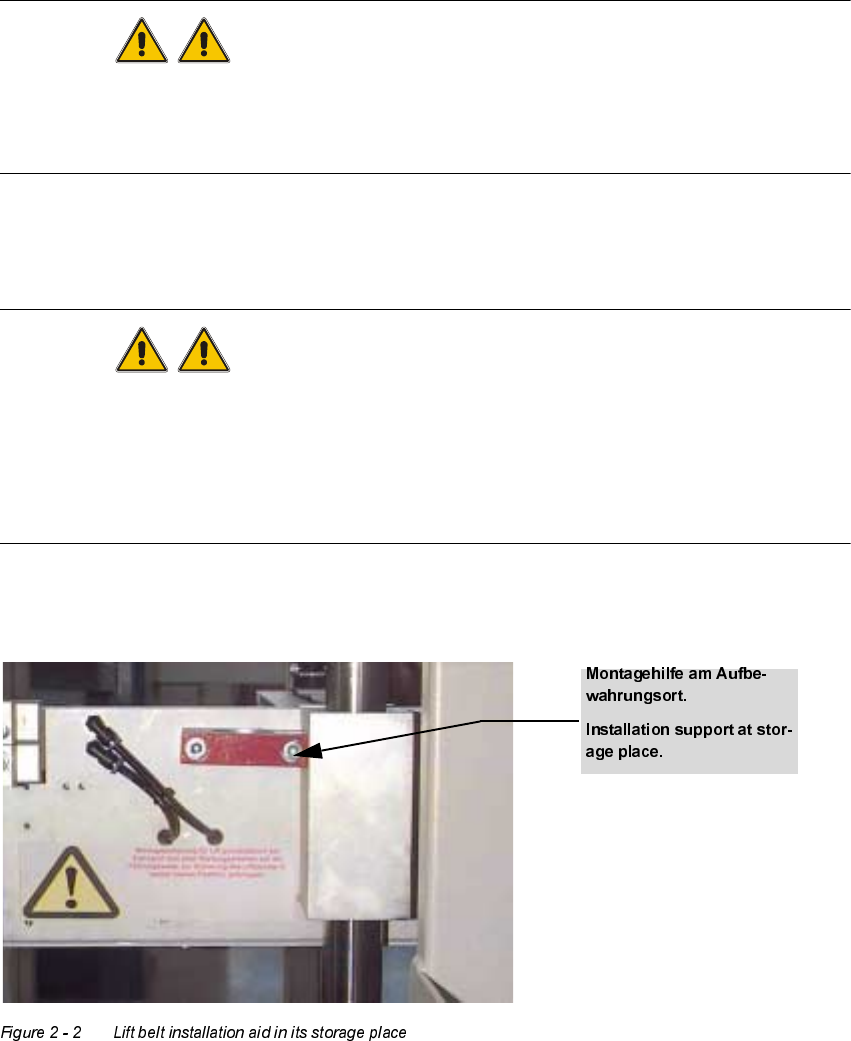
1. The following picture shows where the installation aid is kept when it is not in use.
2 Safety User Manual V 1.15 - Productivity Lift
2.5 Transport and assembly locks Software version V 40.11 Edition 01/2001
14
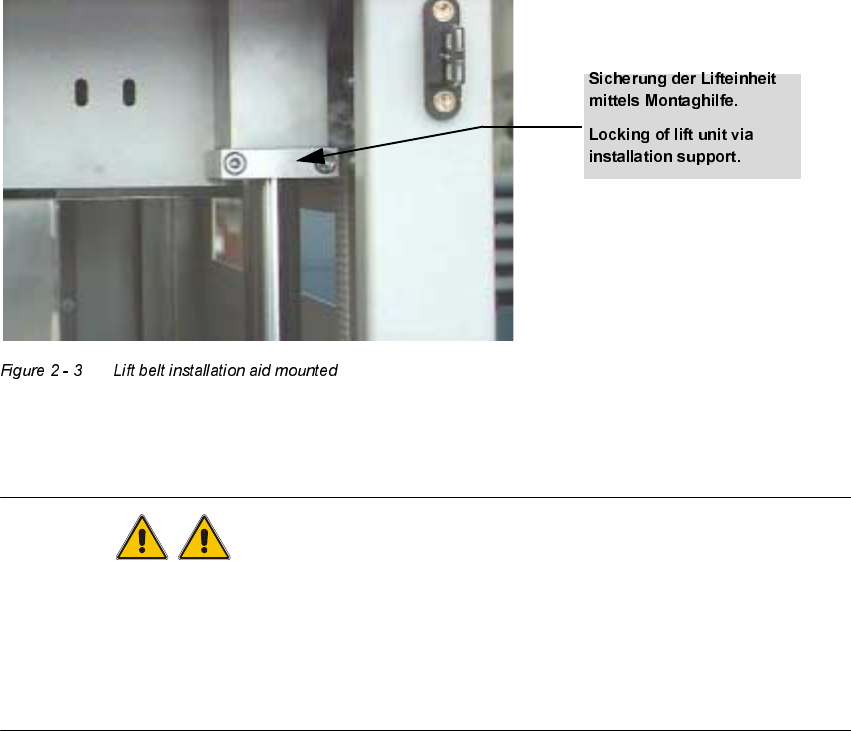
2. Before carrying out any work that is required at either of the two lift units, the installation lock
must be secured as shown in the figure below on the guide shaft underneath the lift. To this
end, the lift must be transported to its uppermost position.
/RFNLQJWKHXSSHUOLIWEHOW
:$51,1*
The installation aid shown in the figures serves to lock the upper lift belt during servicing, mainte-
nance work and transport. Any activity that involves a person having to intervene in any way in the
area between the upper lift belt and the lift belt should result in the following locking measures be-
ing taken as described below. After the activities are finished and before the device is turned on
again all securities have to be removed and to be deposed at the right place.
User Manual V 1.15 - Productivity Lift 2 Safety
Software version V 40.11 Edition 01/2001 2.5 Transport and assembly locks
15
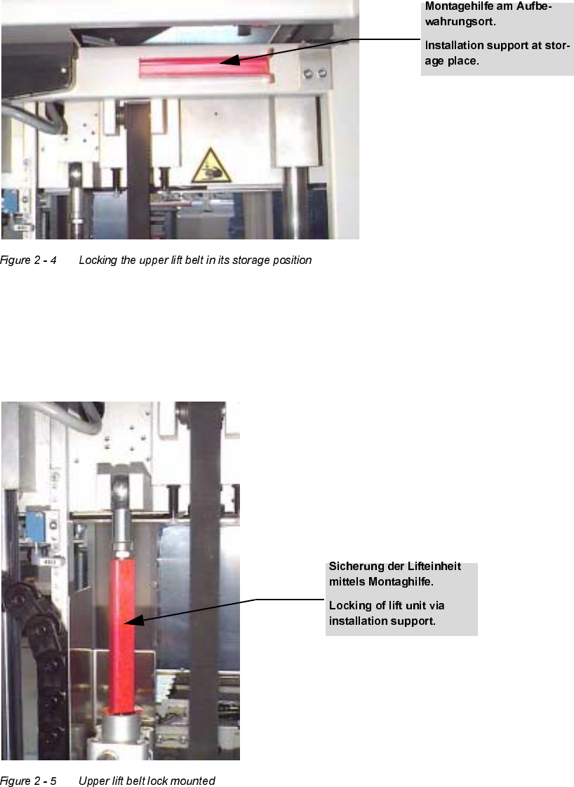
1. The following picture shows where the installation aid is kept when it is not in use.
2. Before carrying out any work that is required at either of the two lift units, the installation lock
must be press-fitted as shown in the figure below on the piston rod of the cylinder. To this end,
the lift must be transported to its uppermost position.