00192809-01 - 第43页
User Manual V 1.15 - Productivity Lift 5 Configuration Software version V 40. 1 1 Edition 01/2001 5.3 Interface 2 35 , QWHUID FH "Interfac e 2" defines th e interfa ce at t he outlet ( n+1) to subsequ ent…
5 Configuration User Manual V 1.15 - Productivity Lift
5.2 Interface 1 Software version V 40.11 Edition 01/2001
34
,QWHUIDFH
"Interface 1" defines the interface at the inlet (n-1) to previous systems.
The available settings are "SMEMA" and "Siemens".
127(
The device is equipped with a defined interface. The interface shown in the display must conform
to the interface installed at the interface module AMI 2-x. It’s possible to change the interface sub-
sequently, but this may only be done by an authorised person.
Interface 1
Siemens
User Manual V 1.15 - Productivity Lift 5 Configuration
Software version V 40.11 Edition 01/2001 5.3 Interface 2
35
,QWHUIDFH
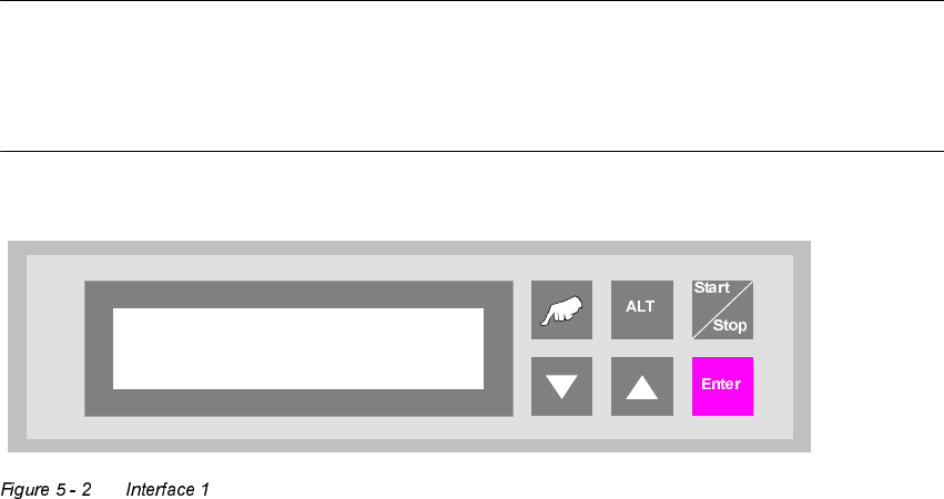
"Interface 2" defines the interface at the outlet (n+1) to subsequent systems.
The available settings are "SMEMA" and "Siemens".
127(
The device is equipped with a defined interface. The interface shown in the display must conform
to the interface installed at the interface module AMI 2-x. It is possible to change the interface sub-
sequently, but this may only be done by an authorised person.
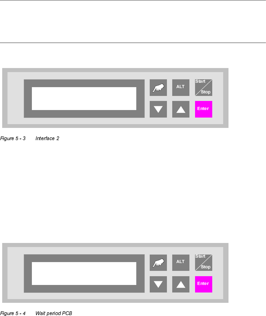
:DLWSHULRG3&%
Time buffer for transferring a printed circuit board. Once this period has elapsed, the belt drive is
switched off and a fault indication is output since no PCB has arrived at the light barrier.
The unit of value is [0.01s] and the setting range is between 300 and 9999, which corresponds to
a time of 3 s to 99.99 s.
Interface 2
Siemens
Wait period PCB
2000
5 Configuration User Manual V 1.15 - Productivity Lift
5.5 Max. time un-belt Software version V 40.11 Edition 01/2001
36
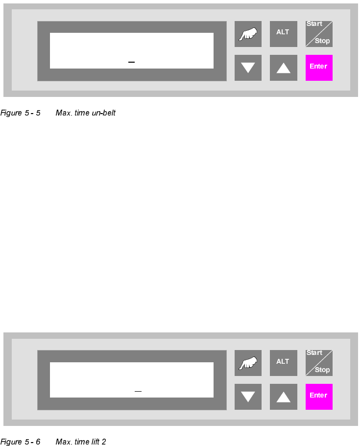
0D[WLPHXQEHOW
If a PCB has not been transferred from the conveyor to the lift after the adjusted time, the auto-
matic operating mode is stopped and the error signal shows "PCB annuated". The PCB is only
then transferred from the conveyor to the following lift when the error signal is confirmed with the
"Enter" cursor through the user.
The unit of the value is [s] and the adjustment area is 0s to 9999s, whereas the function is switched
off for the value 0s.
0D[WLPHOLIW
If the ramp up mode setting is "1 to 0", a PCP can be buffered on track 3 until the transport on
track 1 or track 2 is available again. The selected time defines the waiting period. If the selected
time is exceeded, the PCP is transferred to the buffer on track 3 of the underfloor conveyor. De-
pending on the availability of track 1 and 2 the PCP is transported reverse into the Productivity Lift
for further processing.
The dimension is in [s]. The setting range is between 0 - 600 s.
The feature is turned off by entering "0".
Max. time un-belt
0
Max. time lift 2
000